
Page 151 - Mechatronics for Safety, Security and Dependability in a New Era
P. 151
Ch28-I044963.fm Page 135 Thursday, July 27, 2006 7:12 AM
7:12 AM
Thursday, July 27, 2006
Ch28-I044963.fm
Page 135
135
135
—•Information transfer '
i=>Object transfer
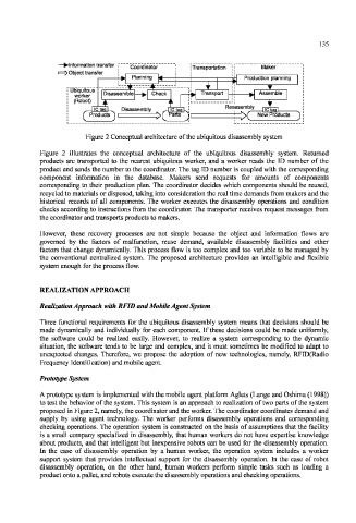
Figure 2 Conceptual architecture of the ubiquitous disassembly system
Figure 2 illustrates the conceptual architecture of the ubiquitous disassembly system. Returned
products are transported to the nearest ubiquitous worker, and a worker reads the ID number of the
product and sends the number to the coordinator. The tag ID number is coupled with the corresponding
component information in the database. Makers send requests for amounts of components
corresponding to their production plan. The coordinator decides which components should be reused,
recycled to materials or disposed, taking into consideration the real time demands from makers and the
historical records of all components. The worker executes the disassembly operations and condition
checks according to instructions from the coordinator. The transporter receives request messages from
the coordinator and transports products to makers.
However, these recovery processes are not simple because the object and information flows are
governed by the factors of malfunction, reuse demand, available disassembly facilities and other
factors that change dynamically. This process flow is too complex and too variable to be managed by
the conventional centralized system. The proposed architecture provides an intelligible and flexible
system enough for the process flow.
REALIZATION APPROACH
Realization Approach with RFID and Mobile Agent System
Three functional requirements for the ubiquitous disassembly system means that decisions should be
made dynamically and individually for each component. If these decisions could be made uniformly,
the software could be realized easily. However, to realize a system corresponding to the dynamic
situation, the software tends to be large and complex, and it must sometimes be modified to adapt to
unexpected changes. Therefore, we propose the adoption of new technologies, namely, RFlD(Radio
Frequency Identification) and mobile agent.
Prototype System
A prototype system is implemented with the mobile agent platform Aglets (Lange and Oshima (1998))
to test the behavior of the system. This system is an approach to realization of two parts of the system
proposed in Figure 2, namely, the coordinator and the worker. The coordinator coordinates demand and
supply by using agent technology. The worker performs disassembly operations and corresponding
checking operations. The operation system is constructed on the basis of assumptions that the facility
is a small company specialized in disassembly, that human workers do not have expertise knowledge
about products, and that intelligent but inexpensive robots can be used for the disassembly operation.
In the case of disassembly operation by a human worker, the operation system includes a worker
support system that provides intellectual support for the disassembly operation. In the case of robot
disassembly operation, on the other hand, human workers perform simple tasks such as loading a
product onto a pallet, and robots execute the disassembly operations and checking operations.