
Page 152 - Mechatronics for Safety, Security and Dependability in a New Era
P. 152
Ch28-I044963.fm Page 136 Thursday, July 27, 2006 7:12 AM
Ch28-I044963.fm
136
136 Page 136 Thursday, July 27, 2006 7:12 AM
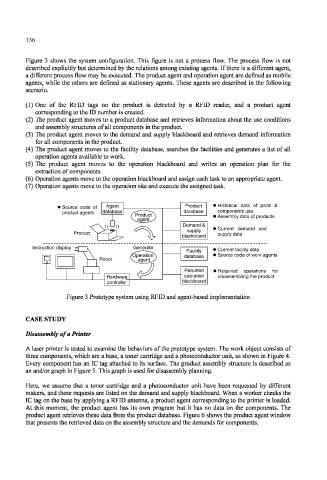
Figure 3 shows the system configuration. This figure is not a process flow. The process flow is not
described explicitly but determined by the relations among existing agents. If there is a different agent,
a different process flow may be executed. The product agent and operation agent are defined as mobile
agents, while the others are defined as stationary agents. These agents are described in the following
scenario.
(1) One of the RFID tags on the product is detected by a RFID reader, and a product agent
corresponding to the ID number is created.
(2) The product agent moves to a product database and retrieves information about the use conditions
and assembly structures of all components in the product.
(3) The product agent moves to the demand and supply blackboard and retrieves demand information
for all components in the product.
(4) The product agent moves to the facility database, searches the facilities and generates a list of all
operation agents available to work.
(5) The product agent moves to the operation blackboard and writes an operation plan for the
extraction of components.
(6) Operation agents move to the operation blackboard and assign each task to an appropriate agent.
(7) Operation agents move to the operation site and execute the assigned task.
Historical data of parts &
Source code of
I Source code of Agent Product • Historical data of parts &
components use
product agents
product agents database database components use
Product • Assembly data of products
Assembly data of products
agent
(( )) Demand &
Current demand and
supply »Current demand and
Product supply data
supply data
blackboard
Instruction display Generate
Instruction display
Current facility data
Facility > Current facility data
Source code of work agents
Operation database > Source code of work agents
Robot agent
Required • Required operations for
Required operations for
disassembling the product
Hardware operation disassembling the product
controller blackboard
Figure 3 Prototype system using RFID and agent-based implementation
CASE STUDY
Disassembly of a Printer
A laser printer is tested to examine the behaviors of the prototype system. The work object consists of
three components, which are a base, a toner cartridge and a photoconductor unit, as shown in Figure 4.
Every component has an IC tag attached to its surface. The product assembly structure is described as
an and/or graph in Figure 5. This graph is used for disassembly planning.
Here, we assume that a toner cartridge and a photoconductor unit have been requested by different
makers, and these requests are listed on the demand and supply blackboard. When a worker checks the
IC tag on the base by applying a RFID antenna, a product agent corresponding to the printer is loaded.
At this moment, the product agent has its own program but it has no data on the components. The
product agent retrieves these data from the product database. Figure 6 shows the product agent window
that presents the retrieved data on the assembly structure and the demands for components.