
Page 298 - Membranes for Industrial Wastewater Recovery and Re-Use
P. 298
Case studies 267
Waste
backwash
basin
RW water
Flocculator
Alkaline bnne regenerant Dual media
filter
I'D1
plant
I'
:;
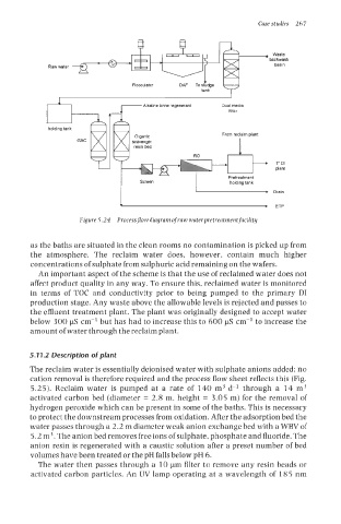
Figure 5.24 Processflow diagram ofraw waterpretreatmentfacility
as the baths are situated in the clean rooms no contamination is picked up from
the atmosphere. The reclaim water does, however, contain much higher
concentrations of sulphate from sulphuric acid remaining on the wafers.
An important aspect of the scheme is that the use of reclaimed water does not
affect product quality in any way. To ensure this, reclaimed water is monitored
in terms of TOC and conductivity prior to being pumped to the primary DI
production stage. Any waste above the allowable levels is rejected and passes to
the effluent treatment plant. The plant was originally designed to accept water
below 300 pS cm-l but has had to increase this to 600 pS cm-l to increase the
amount of water through the reclaim plant.
5.11.2 Description of plant
The reclaim water is essentially deionised water with sulphate anions added: no
cation removal is therefore required and the process flow sheet reflects this (Fig.
5.25). Reclaim water is pumped at a rate of 140 m3 d-l through a 14 m3
activated carbon bed (diameter = 2.8 m, height = 3.05 m) for the removal of
hydrogen peroxide which can be present in some of the baths. This is necessary
to protect the downstream processes from oxidation. After the adsorption bed the
water passes through a 2.2 m diameter weak anion exchange bed with a WBV of
5.2 m3. The anion bed removes free ions of sulphate, phosphate and fluoride. The
anion resin is regenerated with a caustic solution after a preset number of bed
volumes have been treated or the pH falls below pH 6.
The water then passes through a 10 pm filter to remove any resin beads or
activated carbon particles. An UV lamp operating at a wavelength of 18 5 nm