
Page 297 - Membranes for Industrial Wastewater Recovery and Re-Use
P. 297
266 Membranes for lndustrial Wastewater Recover9 and Re-use
Afterwards the wafers are placed in a constantly overflowing deionised (DI)
water bath and then onto a second rinse stage before moving onto the next stage
of production. The DI water can be either hot or cold, depending on the acid bath
temperature, and is drained separately from the bench before being pumped to
the treatment facility.
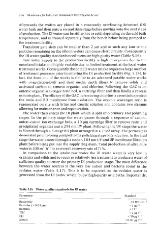
Transistor gate sizes can be smaller than 2 pm and as such any ions or the
particles remaining on the silicon wafers can cause short circuits. Consequently
the DI water quality standards need to ensure high-purity water (Table 5.16).
Raw water supply to the production facility is high in organics due to the
moorland intake and highly variable due to limited treatment at the local water
treatment works. Consequently the potable water intake requires a large number
of treatment processes prior to entering the DI production facility (Fig. 5.24). In
fact, the front end of the works is similar to an advanced potable water works
with coagulation-DAF and dual media depth filters to remove solids and
activated carbon to remove organics and chlorine. Following the GAC is an
anionic organic scavenger resin bed, a cartridge filter and then finally a reverse
osmosis plant. The efficacy of the GAC in removing chlorine is essential to protect
the resin and RO membrane from oxidation. The organic scavenger resin is
regenerated on site with brine and caustic solution and contains two streams
allowing for maintenance and regeneration.
The water then enters the DI plant which is split into primary and polishing
stages. In the primary stage the water passes through a sequence of cation-
anion-cation ion exchange beds, a 10 pm cartridge filter to remove resin and
precipitated organics and a 254 nm UV plant. Following the UV stage the water
is filtered through a 3-stage RO plant arranged in a 7:3:2 array. The permeate is
de-aerated prior to being pumped to the polishing stage of production. In the final
stage the water passes through a cooler, 185 nm UV and IJF membrane filtration
plant before being put into the supply ring main. Total production of ultra pure
water is 200 m3 h-’ at an overall recovery rate of 71%.
In comparison to the intake raw water the DI waste water is very low in
organics and solids and so requires relatively less treatment to produce a water of
sufficient quality to enter the primary DI production stage. The main difference
between the water sources is the very low cation and bacteria count in the
reclaim water (Table 5.17). This is to be expected as the reclaim water is
generated from the DI baths, which follow high-purity acid baths. Importantly,
Table 5.16 Water quality standards for DI water
Parameter Standard
Resistivity 18 MC2 cm-2
Particles ( > 0.05 pm) < 5 ml-’
Bacteria < 1 I-’
TOC < 2 pg 1-1
DO < 50 pg 1-I
Metals < 0.01 pg 1-1