
Page 294 - Membranes for Industrial Wastewater Recovery and Re-Use
P. 294
Case studies 263
A
PAINTTANK -+ A A A A A A &”l A
I,
UF :Ulb.nlb.1.
UFR : Ult~lttnb ncycle
DW :Deminenliud water
RP : Recoverad paint
RW : Recovered water
T
ULTRAFILTRATION SYSTEMS
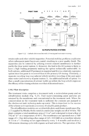
Figure 5.22 Cnthonir electrocoat line with UF rinsingand rinse water recovery
retains salts and other soluble impurities. Potential stability problems could arise
when subsequent paint layers are coated, resulting in a poor quality finish. The
impurities can be removed by utilising reverse osmosis membranes to further
purify the rinse water (option 2). However, the feed to the RO system is likely to
have a high fouling propensity making the option technically undesirable. In
both options, additional UF permeate is required and this is a relatively expensive
option since less paint is recovered than in the primary UF rinsing. Ultimately, a
separate recycling loop was selected which involves recycling of the post-paint
rinse water and recovery of paint (option 3). An additional benefit of option 3 is
that a small concentration of solvent builds up within the loop which improves
the efficacy of the rinsing solution over that of deionised water.
5.70.2 Plant description
The treatment train comprises a treatment tank, a recirculation pump and an
ultrafiltration module (Fig. 5.2 3). Used water-containing paint particles are
retained by the membrane and concentrated in the treatment tank. When the
concentration in the treatment tank is sufficient the contents are pumped to
the electrocoat tank replacing make-up water. This is important to the success
of the scheme as it represents a recovery of valuable paint product.
The ultrafiltration modules are acrylonitrile plate-and-frame membranes (Fig.
2.7) supplied by Rhodia Orelis rated at a molecular weight cut off of 50 kDa. The
plant contains a total membrane area of 5 5 m2 and is designed to treat a flow of
192 m3 d-’ at a temperature of 40°C. The membranes are operated over a TMP
range of 1-3 bar delivering a flux range of 145-300 LMH at a cross flow velocity
of 2.6 m s-l. Cleaning occurs approximately every 3-4 months and involves a
300-minute cleaning cycle with organic acid and solvents. The operation of the