
Page 35 -
P. 35
24 1 From Optical MEMS to Micromechanical Photonics
U-shaped LD
PD
Microlens
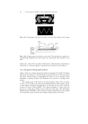
Fig. 1.31. Photograph of the optical encoder. Courtesy of R. Sawada, NTT, Japan
Slider
LD–PD
h1
a-SiN:H
h0 h
GeAsTe
a-SiN:H h2
Au
a-SiN:H
Substrate
Fig. 1.32. A flying optical head with a laser diode. The optical head consists of a
monolithically integrated laser diode (LD)and a photodiode (PD)attached to the
slider
mirror and −2πx/Λ for the other etched mirror. The intensity of interference
caused by the refracted lights is expressed as a function of period 4πx/Λ.
1.4.4 Integrated Flying Optical Head
Figure 1.32 shows a flying optical head with an integrated LD [1.69]. The flying
optical head consists of a monolithically integrated LD and a PD attached to
the slider. Autofocusingis accomplished by means of an air bearing, which
maintains a spacingof 2 µm and eliminates the need for a focusingservo
system.
The sensingpart of the head is an LD integrated with a PD, as shown
in Fig. 1.33. To reduce the light beam width parallel to the junction plane,
a taper-ridged waveguide was fabricated on the edge of the diode cavity by
reactive ion beam etching (RIBE). The ridged waveguide is 1.3 µm wide and
the groove is 3 µm deep, which is deeper than the active layer. The full widths
half-maximum (FWHM) of the near-field pattern perpendicular and parallel
to the junction plane are 0.65 and 0.85 µm, respectively, at the facet.