Page 71 -
P. 71

60    2 Extremely Short-External-Cavity Laser Diode
                                    (a)                           (b)
                                         R (HRC)  R (ARC)  h  R  l           R  h
                                          1       2                           3
                                                              3
                                                                 R
                                                             R  h  3
                                           P           P      3
                                            1           2             Light output
                                       PD        LD
                                                                           R  l  Data signal
                                                                            3
                                                    eff                     l  h  l
                                                   R 2                      th  l th
                                                                           Bias current
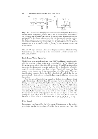
                            Fig. 2.35. LD used in an OSL flying head forms a complex cavity with the recording
                            medium acting as an external mirror. (a) R 1 and R 2 are the power reflectivities of
                                                   l
                                             h
                            the LD facets, and R 3 and R 3 are those of the two states for the external recording
                                     eff
                            medium. R 2 is the effective reflectivity coupled with the external recording medium.
                            (b) Light output versus bias current in the two medium reflectivity states. There
                                                   h
                                                                     l
                                                               l
                                                         h
                            are two threshold currents: I th for R 3 and I th for R 3 . Data bits are read as the laser
                                         l
                                                                    l
                                              h
                                                             h
                            switches from R 3 to R 3 , biased between I th and I th ,bythePD on theoppositeside
                            of the medium
                            The last SiN layer increases adhesion to the glass substrate. The reflectivity,
                            transmitivity, and absorptivity of the as-deposited GeSbTe medium were
                            0.24, 0.22, and 0.54.
                            Basic Read/Write Operation
                            The LD used in an optically switched laser (OSL) head forms a complex cavity
                            with the recordingmedium actingas an external mirror. In Fig. 2.35a, R 1 and
                                                                                l
                                                                          h
                            R 2 are the power reflectivities of the LD facets, and R and R are those of the
                                                                          3
                                                                                3
                            two states for the external recordingmedium. R eff  is the effective reflectivity
                                                                      2
                            coupled with the external recording medium. Figure 2.35b shows the light
                            output versus bias current in the two medium reflectivity states. There are
                                                                            h
                            two threshold currents: I h  for the high reflectivity R and I l  for the low
                                                  th                        3      th
                                       l
                            reflectivity R . Data bits are read as the light output difference between the
                                       3
                            two states.
                               Data bits are written, in this experiment, as the laser-induced phase change
                                                             l
                                                                                 h
                            shifts the medium reflectivity from R (as depo. state) to R (crystal state).
                                                             3                   3
                            During the write operation, the light output changes from P w to P     at a
                                                                                         w
                            fixed write current of I w according to the reflectivity change. The light output
                            difference P − P R (nearly equals to P − P w ) is less than 1 mW, which does


                                      R                      w
                            not destroy the information even if the medium stops. If the light output
                            were 20 mW, the variation ratio in the write process would be only 5%. We,
                            thereby achieve stable write operation. To increase the signal-to-noise ratio
                            (SNR) and light output from the medium side laser facet, the medium side
                            LD facet is coated with an antireflection film of (SiO) (Si 3 N 4 ) 1−x [2.14].
                                                                           x
                            Data Signal
                            Data signals are obtained by the light output difference due to the medium
                            reflectivity. Varyingthe medium reflectivity R 3 as a parameter, Figs. 2.36a
   66   67   68   69   70   71   72   73   74   75   76