Page 73 -
P. 73

62    2 Extremely Short-External-Cavity Laser Diode
                                             (a)                (b)
                                                       access codes   access codes
                                                       WA             WA
                                                       CLK            CLK
                                                       WB             WB


                                              Laser Beam

                                                           1.6 mm

                                                unique distance
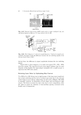
                            Fig. 2.37. Discrete block format (DBF)marks with a 1.6-µm track-pitch (a),and
                            reproduced signals at 900 rpm. LD bias current is 40 mA (b)

                                       Recording
                                       medium
                                                                           Sampling
                                                        RF AMP    PLL      timing
                                       LD                                  generator

                                       PD
                                                                  WA
                                                         Register  +       TE  Track
                                                   A/D                 D/A     error
                                                                   -
                                                         Register              signal
                                                                  WB
                            Fig. 2.38. Block diagram of track error signal detection. Track error signal is ob-
                            tained by the signal amplitude difference between the two wobbling signals of the
                            discrete block format (DBF)


                            derived from the difference in signal amplitudes between the two wobbling
                            signals.
                               Figure 2.38 is a block diagram of the track error signal (TE = WA − WB)
                            detection system. The reproduced track error signal confirms that the spot
                            diameter of the lensless but taper-ridged waveguide LD is small enough to
                            reproduce the DBF servo marks.


                            Reducing Laser Noise by Optimizing Bias Current
                            The SNR of the OSL flying head is high because of the large signal amplitude
                            due to laser switchingand the lack of feedback laser noise due to the external
                            cavity beingso much shorter (2 µm) than the LD cavity (300 µm). The SNR
                            is degraded, however, by fluctuation of both high- and low-frequency light
                            output. The former is caused by laser noise due to mode competition, while
                            the latter is caused by variation of head-medium spacing(external cavity
                            length) and of temperature.
   68   69   70   71   72   73   74   75   76   77   78