
Page 72 -
P. 72
2.4 Applications 61
(a) 25 (b) 25
h = 2mm 0.5 h = 2mm 0.5
= 0.32 0.4 20 R 1 0.4 0.2
= 0.32
R 1
20
Light output (mW) 15 (LD#1) 0.1 =0.0 Light output (mW) 15 (LD#2) 0.1 3
0.3
= 0.01 0.3
= 0.01
R 2
0.2
R 2
10
10
R 3
R =0.0
0 5 5 0
0 1 2 3 4 5 6 0 .5 1 1.5 2 2.5
Current l/l th Current I/I th
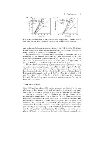
Fig. 2.36. OSL head light output characteristics with the medium reflectivity R 3
as a parameter for (a)an LD#1 (λ =1.3 µm), (b)an LD#2 (λ =0.83 µm)
and b plot the light output characteristics of the OSL head for LD#1 and
LD#2, respectively. These values are calculated for the steady state single-
mode operation by usingthe rate equations [2.26].
The external cavity can be described by replacingmedium side laser facet
eff
reflectivity R 2 by effective reflectivity R . The reflectivities R 2 , R 3 ,and
2
eff
the couplingcoefficient η are included in R . We define η as (2.8). As for
2
0
an LD#2, Gaussian half-power beam width 25 (2w s0 =1.38 µm) and 10 0
(2w p0 =2.54 µm), η is 0.5 for h =2 µm and 0.75 for h =1 µm.
Since the LD facet reflectivity R 2 facingthe medium is greatly reduced by
an antireflection coatingto improve the SNR, the light output P 1 (PD side)
differs from P 2 (medium side). The light output ratio for a complex cavity
laser is calculated usingeffective reflectivity R eff instead of R 2 , as shown in
2
Problem 2.3. For example, with h =2, P 2 /P 1 =1.5for R 1 =0.32,R 2 =0.01,
and R 3 =0.3; P 2 /P 1 =5 for R 1 =0.70,R 2 =0.01, and R 3 =0.3(see
Fig. A.3). We used these ratios to estimate read/write power P 2 from the
measured light output P 1 .
Track Error Signal
Since OSL head has only one PD, track error signals are obtained by the sam-
pled servo method instead of the push–pull method for the continuous servo.
Sampled servo method is expected to give good stability and compatibility.
Discrete block format (DBF) [2.27] marks with a 1.6-µm track-pitch are
reproduced by the OSL flyinghead as shown in Fig. 2.37. They are preformat-
ted on the glass substrate in phase pits. Figure 2.37a shows a DBF mark with
two access codes and three patterns, different in phase, that correspond to the
wobble A (WA), clock (CLK), and wobble B (WB). Figure 2.37b shows repro-
duced signals. Each pulse composed of five peaks, represents the servo signals
(DBF mark) at the beginning of each 1,672 block per revolution. The third
and the fifth peaks are wobblingsignals, WA and WB, whose marks are dis-
placed +1/4and −1/4 pitches from the track center. Track error signals were