
Page 234 - A Practical Guide from Design Planning to Manufacturing
P. 234
206 Chapter Seven
V goes low, V out is able to follow all the way to the ground voltage, and
in
current continues to flow in the NMOS until V and V out are equal.
in
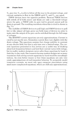
PMOS devices have the opposite problem. Because PMOS devices
will switch off if both source and drain are only a threshold voltage
above the gate, a PMOS with its gate tied to ground cannot pull its
drain to ground. The resulting waveform when this is tried is shown in
Fig. 7-5.
The inability of NMOS devices to pull high and PMOS devices to pull
low is why almost all logic gates use both types of devices in order to
make sure the output of the gate can be switched through the full range
of voltages.
The MOSFET current equations are only approximations. Current in
cutoff is not exactly zero. Saturation current does vary slightly with the
drain voltage. The equations assume that charge mobility is constant
at any electric field, but this is only true over a limited range. The cur-
rent equations presented in this section are a useful way of thinking
about how transistors behave and how their current varies with voltage,
but in reality modern designers never solve these equations by hand in
their day-to-day work. One reason is because modern designs use so many
transistors that solving current equations by hand would be exceedingly
tedious. An even better reason is that these equations are only very
crude approximations of real transistor behavior. To accurately model
transistor currents, we must rely upon computer simulations using
much more complicated equations, which are still only approximations.
V dd
V ss
Voltage
V in V out V in V out
V t
V ss
Time
Figure 7-5 PMOS pulling low.