
Page 238 - A Practical Guide from Design Planning to Manufacturing
P. 238
210 Chapter Seven
schematic) to the supply line. If either turns on, the output will be drawn
to a 1. The N-transistors are connected in series from the output to
the ground line. Only if both turn on, the output will be drawn to a 0.
The two inputs, A and B, are each connected to the gate of one P-transistor
and one N-transistor.
Starting at the bottom left of Fig. 7-10, the NAND circuit is shown
with both inputs at 0. Both N-devices will be off and both P-devices will
be on, pulling the output to a 1. The middle two cases show that if only
one of the inputs is 0, one of the N-devices will be on, but it will be in
series with the other N-device that is off. A 0 signal is blocked from the
output by the off N-device, and the single on P-device still pulls the output
to a 1. At the bottom right, the final case shows that only if both inputs
are high and both N-devices are on, the output is pulled to a 0.
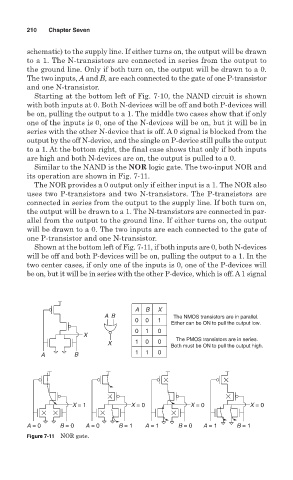
Similar to the NAND is the NOR logic gate. The two-input NOR and
its operation are shown in Fig. 7-11.
The NOR provides a 0 output only if either input is a 1. The NOR also
uses two P-transistors and two N-transistors. The P-transistors are
connected in series from the output to the supply line. If both turn on,
the output will be drawn to a 1. The N-transistors are connected in par-
allel from the output to the ground line. If either turns on, the output
will be drawn to a 0. The two inputs are each connected to the gate of
one P-transistor and one N-transistor.
Shown at the bottom left of Fig. 7-11, if both inputs are 0, both N-devices
will be off and both P-devices will be on, pulling the output to a 1. In the
two center cases, if only one of the inputs is 0, one of the P-devices will
be on, but it will be in series with the other P-device, which is off. A1 signal
A B X
AB The NMOS transistors are in parallel.
0 0 1
Either can be ON to pull the output low.
0 1 0
X
The PMOS transistors are in series.
X 1 0 0
Both must be ON to pull the output high.
A B 1 1 0
X = 1 X = 0 X = 0 X = 0
A = 0 B = 0 A = 0 B = 1 A = 1 B = 0 A = 1 B = 1
Figure 7-11 NOR gate.