
Page 287 - A Practical Guide from Design Planning to Manufacturing
P. 287
Layout 257
Layout also has a large impact on circuit noise. As described in Chap. 7,
one of the largest sources of electrical noise is cross talk between wires.
The switching of one wire causes a neighboring wire to be pulled from
its ideal voltage. Layout can alleviate this problem by paying special
attention to which signals are routed next to one another. Routing a sen-
sitive signal wire to minimize cross talk noise is called shielding.
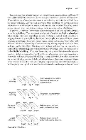
Figure 8-14 shows three ways of reducing noise on the signal A (SigA)
wire by shielding. The simplest and most effective method is physical
shielding. Physical shielding means routing a signal next to either a
supply line or a ground line. Because the supply and ground lines never
change in voltage, they will never cause cross talk noise. They also will
reduce the noise induced by other sources by adding capacitance to a fixed
voltage to the SigA line. Routing with a fixed voltage line on one side is
called half shielding and routing with fixed voltage lines on both sides is
called full shielding. Whether the supply or ground line is used does not
matter. What is important is that the neighboring lines are carrying a
constant voltage. Physical shielding is very effective, but also expensive
in terms of wire tracks. A fully shielded signal line now occupies three
wire tracks instead of just one. Trying to physically shield many signals
will rapidly use up all the available wire tracks and require layout area
Both neighbors can switch
No
in the same direction at
shielding
the same time.
Sig B Sig A Sig C
Physical
shielding Neighbors can not switch.
V ss Sig A V dd
Temporal Neighbors can not both
shielding switch at the same time.
Sig BH Sig A Sig CL
Logical Neighbors can not both
shielding switch in the same direction.
Sig B Sig A Sig B
Figure 8-14 Shielding.