
Page 49 - A Practical Guide from Design Planning to Manufacturing
P. 49
The Evolution of the Microprocessor 25
thickness (T INT ) is equal to the vertical spacing of wires (T ILD ), capaci-
tance per length (C ) is approximated by the following equation. 7
L
T W
C = C + C + C + C ≈ 2 Kε INT + INT
L LEFT RIGHT UP DOWN 0 W SP T I ILD
Wire capacitance is kept to a minimum by using small wires and wide
spaces, but this reduces the total number of wires that can fit in a given
area and leads to high wire resistance. The delay for a voltage signal to
travel a length of wire (L WIRE ) is the product of the resistance of the wire
and the capacitance of the wire, the RC delay. The wire resistance per
length (R ) is determined by the width and thickness of the wire as well
L
as the resistivity (r) of the material.
ρ
R =
L ×
W T
INT INT
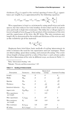
Engineers have tried three basic methods of scaling interconnects in
order to balance the need for low capacitance and low resistance. These
8
are ideal scaling, quasi-ideal scaling, and constant-R scaling. For a wire
whose length is being scaled by a value S less than 1, each scheme scales
the other dimensions of the wire in different ways, as shown in Table 1-1.
7
Bohr, “Interconnect Scaling,” 106.
8
Bakoglu, “Circuits and Interconnections,” 197.
TABLE 1-1 Scaling of Interconnects
Quasi-ideal
Description Parameter Ideal scaling scaling Constant-R scaling
Length L WIRE S S S
Width W INT S S S
Spacing W SP S S S
Thickness T INT S S S
Interlevel dielectric T ILD S S S
Aspect ratio T INT /W INT 1 1/ S 1
Wire capacitance C L 1 1/S 0.1 1
per length
Wire capacitance C L L WIRE S S 0.9 S
Wire resistance R L 1/S 2 1/S 1.5 1/S
per length
Wire resistance R L L WIRE 1/S 1/S 0.5 1
RC delay R L C L L WIRE 2 1 S 0.4 S