
Page 249 - Microsensors, MEMS and Smart Devices - Gardner Varadhan and Awadelkarim
P. 249
INTRODUCTION 229
Amplifier Actuator
Out
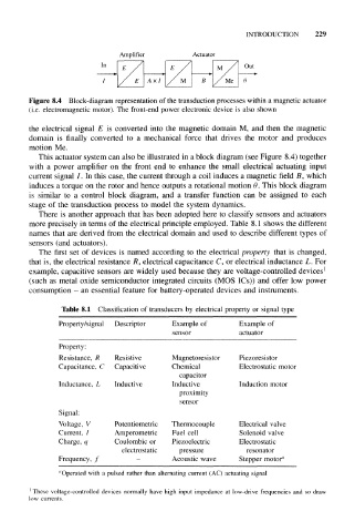
Figure 8.4 Block-diagram representation of the transduction processes within a magnetic actuator
(i.e. electromagnetic motor). The front-end power electronic device is also shown
the electrical signal E is converted into the magnetic domain M, and then the magnetic
domain is finally converted to a mechanical force that drives the motor and produces
motion Me.
This actuator system can also be illustrated in a block diagram (see Figure 8.4) together
with a power amplifier on the front end to enhance the small electrical actuating input
current signal /. In this case, the current through a coil induces a magnetic field B, which
induces a torque on the rotor and hence outputs a rotational motion 9. This block diagram
is similar to a control block diagram, and a transfer function can be assigned to each
stage of the transduction process to model the system dynamics.
There is another approach that has been adopted here to classify sensors and actuators
more precisely in terms of the electrical principle employed. Table 8.1 shows the different
names that are derived from the electrical domain and used to describe different types of
sensors (and actuators).
The first set of devices is named according to the electrical property that is changed,
that is, the electrical resistance R, electrical capacitance C, or electrical inductance L. For
1
example, capacitive sensors are widely used because they are voltage-controlled devices
(such as metal oxide semiconductor integrated circuits (MOS ICs)) and offer low power
consumption - an essential feature for battery-operated devices and instruments.
Table 8.1 Classification of transducers by electrical property or signal type
Property/signal Descriptor Example of Example of
sensor actuator
Property:
Resistance, R Resistive Magnetoresistor Piezoresistor
Capacitance, C Capacitive Chemical Electrostatic motor
capacitor
Inductance, L Inductive Inductive Induction motor
proximity
sensor
Signal:
Voltage, V Potentiometric Thermocouple Electrical valve
Current, / Amperometric Fuel cell Solenoid valve
Charge, q Coulombic or Piezoelectric Electrostatic
electrostatic pressure resonator
Frequency, f - Acoustic wave Stepper motor a
"Operated with a pulsed rather than alternating current (AC) actuating signal
These voltage-controlled devices normally have high input impedance at low-drive frequencies and so draw
low currents.