
Page 403 - Microsensors, MEMS and Smart Devices - Gardner Varadhan and Awadelkarim
P. 403
APPLICATIONS 383
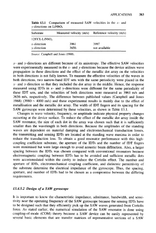
Table 13.1 Comparison of measured SAW velocities in the x- and
y -directions on LiNbO 3
Substrate Measured velocity (m/s) Reference velocity (m/s)
128YX-LiNbO 3
x-direction 3961 3997
y-direction 3656 not available
Source: Campbell and Jones (1968).
x- and y-directions are different because of its anisotropy. The effective SAW velocities
were experimentally measured in the x- and y-directions because the device utilises wave
propagation in these directions and the effect of the metallic dot array on the velocities
in both directions is not fully known. To measure the effective velocities of the waves in
both directions, two narrow-band IDT sets with the same periodicity were placed in the
x- and y-direction so that they included the dot array in the middle. Hence, the response
measured using IDTs in x- and y-directions were different for the same periodicity of
these IDT sets, and the velocities of both directions were measured as 3961 m/s and
3656 m/s, respectively. The difference between published values (Campbell and Jones
1968) (3980 ~ 4000 m/s) and these experimental results is mainly due to the effect of
metallisation and the metallic dot array. The width of IDT fingers and its spacing for the
SAW gyroscope were determined by these velocities, as shown in Table 13.1.
Changes in wave velocity, frequency, or amplitude indicate physical property changes
occurring at the device surface. To reduce the effect of the metallic dot array inside the
SAW resonator, the size of each dot in the array was chosen such that it is sufficiently
smaller than the wavelength in both directions. Because the amplitudes of the standing
waves are dependent on material damping and electromechanical transduction losses,
the transmitting and sensing IDTs are located at the standing wave maxima in order to
reduce the transduction loss. To obtain a good resonator performance with this high-
coupling coefficient substrate, the aperture of the IDTs and the number of IDT fingers
were minimised but were large enough to avoid acoustic beam diffraction. Also, a larger
spacing between the IDTs was chosen compared with conventional resonators because
electromagnetic coupling between IDTs has to be avoided and sufficient metallic dots
were accommodated within the cavity to induce the Coriolis effect. The number and
aperture of IDTs, electromechanical coupling coefficient, and dielectric permittivity of
the substrate determine the electrical impedance of the gyroscope. Thus, the spacing,
aperture, and number of IDTs had to be chosen as a compromise between the differing
requirements.
13.4.5.2 Design of a SAW gyroscope
It is important to know the characteristic impedance, admittance, bandwidth, and sensi-
tivity near the operating frequency of the SAW gyroscope because the sensing IDTs have
to be designed such that they efficiently pick up the SAW waves generated from Coriolis
force. As stated earlier, the numerical simulation of the SAW resonator is done using
coupling-of-mode (COM) theory because a SAW device can be easily represented by
several basic elements that are transfer matrices of representative sections of a SAW