
Page 408 - Microsensors, MEMS and Smart Devices - Gardner Varadhan and Awadelkarim
P. 408
388 IDT MICROSENSORS
By applying the aforementioned boundary conditions, 2 x 2 matrix equation could be
solved:
(13.86)
The output voltage V out (S 21) from the IDT can be written as
Vout = b 5 = [T S5][W 5] (13.87)
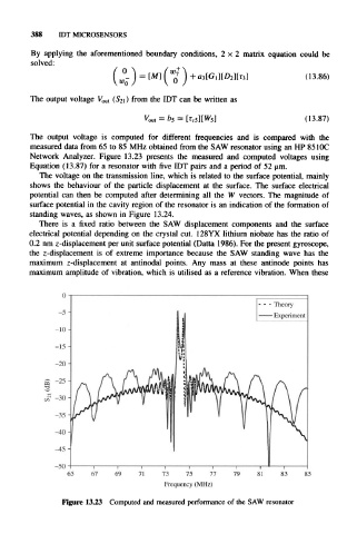
The output voltage is computed for different frequencies and is compared with the
measured data from 65 to 85 MHz obtained from the SAW resonator using an HP 85 I0C
Network Analyzer. Figure 13.23 presents the measured and computed voltages using
Equation (13.87) for a resonator with five IDT pairs and a period of 52 um.
The voltage on the transmission line, which is related to the surface potential, mainly
shows the behaviour of the particle displacement at the surface. The surface electrical
potential can then be computed after determining all the W vectors. The magnitude of
surface potential in the cavity region of the resonator is an indication of the formation of
standing waves, as shown in Figure 13.24.
There is a fixed ratio between the SAW displacement components and the surface
electrical potential depending on the crystal cut. 128YX lithium niobate has the ratio of
0.2 nm z-displacement per unit surface potential (Datta 1986). For the present gyroscope,
the z-displacement is of extreme importance because the SAW standing wave has the
maximum z-displacement at antinodal points. Any mass at these antinode points has
maximum amplitude of vibration, which is utilised as a reference vibration. When these
-50
73 75 77
Frequency (MHz)
Figure 13.23 Computed and measured performance of the SAW resonator