
Page 412 - Microsensors, MEMS and Smart Devices - Gardner Varadhan and Awadelkarim
P. 412
392 IDT MICROSENSORS
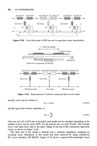
Figure 13.28 Cross-field model of IDT pair and its equivalent circuit representation
Figure 13.29 Representation of reflectors using equivalent circuit model
acoustic wave can be written as
zm = PA (13.91)
and the equivalent electric impedance is
Zm
20 = - (13.91)
42
Once the unit cell of IDT pair is modeled, each model can be cascaded, depending on the
number of pairs for the sensor IDTs. For the present case, we used 30 pairs. The Coriolis
force is the input force, that is, the input voltage at one end of the constructed equivalent
circuit, as shown in Figure 13.28.
The other end of the model is shorted with a substrate impedance, assuming no
incoming wave. Simulation of this model has been achieved by using commercial
RF circuit simulator, HP EESOF. Figure 13.30 shows a typical half-wavelength circuit