
Page 414 - Microsensors, MEMS and Smart Devices - Gardner Varadhan and Awadelkarim
P. 414
394 IDT MICROSENSORS
V_AC
SRC1 Thirty periods
Voc = polar (Veq.O) V Thirty periods 1 R6
Freq = freq R = Zos
Probe
gyro output
AC
AC
AC1
Start = 70 MHz
Stop = 80 MHz
Step = 10 MHz
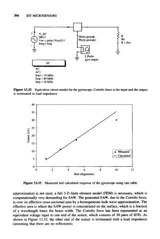
Figure 1332 Equivalent circuit model for the gyroscope. Coriolis force is the input and the output
is terminated to load impedance
40
35-
30-
^ 25-
^ 20-
•3
o.
° 15-
10-
5-
0
0 4 6 10 12
Rate (degree/sec)
Figure 1333 Measured and calculated response of the gyroscope using rate table
approximation is not used, a full 3-D finite element model (FEM) is necessary, which is
computationally very demanding for SAW. The generated SAW, due to the Coriolis force,
is over its effective cross-sectional area by a homogeneous bulk wave approximation. The
effective area is where the SAW power is concentrated on the surface, which is a fraction
of a wavelength times the beam width. The Coriolis force has been represented as an
equivalent voltage input to one end of the sensor, which consists of 30 pairs of IDTs. As
shown in Figure 13.32, the other end of the sensor is terminated with a load impedance
(assuming that there are no reflections).