
Page 418 - Microsensors, MEMS and Smart Devices - Gardner Varadhan and Awadelkarim
P. 418
398 MEMS-IDT MICROSENSORS
is possible to create a wireless MEMS-IDT microsensor in a manner similar to that was
shown as possible to make a wireless IDT microsensor in Chapter 13 (Subramanian et al.
1997).
14.2 PRINCIPLES OF A MEMS-IDT ACCELEROMETER
The Rayleigh wave is a surface wave in which the wave energy is almost completely
confined within a distance of one wavelength above the substrate (Ballantine et al. 1997).
There are basically two types of boundary conditions applicable with the surface of the
piezoelectric being mechanically free. In one form, the surface has a thin conductive layer.
This layer does not alter the mechanical boundary conditions but causes the surface to
be equipotential and the propagating potential to be zero at the surface of the substrate.
The other case is the one in which the surface is electrically free and the potential above
the surface follows Laplace's equation. The potential vanishes as the distance above the
1
substrate approaches infinity .
In a MEMS-IDT accelerometer, a conductive seismic mass is placed close to the
substrate (at a distance of less than one acoustic wavelength). This serves to alter the
electrical boundary condition discussed earlier. The seismic mass can be fabricated from
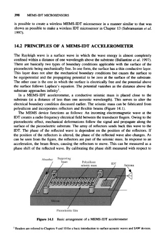
polysilicon and incorporates reflectors and flexible beams (Figure 14.1).
The MEMS device functions as follows: An incoming electromagnetic wave at the
IDT creates a radio frequency electrical field between the transducer fingers. Owing to the
piezoelectric effect, mechanical deformations follow the signal and propagate along the
surface of the piezoelectric substrate. The array of reflectors sends back this wave to the
IDT. The phase of the reflected wave is dependent on the position of the reflectors. If
the position of the reflectors is altered, the phase of the reflected wave also changes. As
can be seen from the figure, the reflectors are part of the seismic mass. In response to an
acceleration, the beam flexes, causing the reflectors to move. This can be measured as a
phase shift of the reflected wave. By calibrating the phase shift measured with respect to
Figure 14.1 Basic arrangement of a MEMS-IDT accelerometer
1
Readers are referred to Chapters 9 and 10 for a basic introduction to surface acoustic waves and SAW devices.