
Page 423 - Microsensors, MEMS and Smart Devices - Gardner Varadhan and Awadelkarim
P. 423
TESTING OF A MEMS-IDT ACCELEROMETER 403
of the microsensor (Section 14.4.1–14.4.4). Then we will discuss the incorporation of a
seismic mass to produce an inertial accelerometer (Section 14.4.5).
14.4.1 Measurement Setup
The vector network analyser and associated calibration techniques make it possible to
3
measure accurately the reflection and transmission parameters of devices under test .
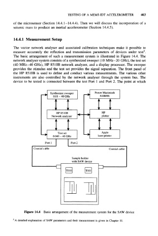
The basic arrangement of such a measurement system is illustrated in Figure 14.4. The
network analyser system consists of a synthesized sweeper (10 MHz–20 GHz), the test set
(40 MHz-40 GHz), HP 8510B network analyzer, and a display processor. The sweeper
provides the stimulus and the test set provides the signal separation. The front panel of
the HP 8510B is used to define and conduct various measurements. The various other
instruments are also controlled by the network analyser through the system bus. The
device to be tested is connected between the test Port 1 and Port 2. The point at which
Synthesizer sweeper Power Macintosh
0.01 – 40 GHz 6100/66
A A A
V JL V
HP 8510B HP
Network analyzer plotter
Test set Apple
0.045 - 40 GHz laser printer
Port 1 Port 2
Coaxial cable Coaxial cable
Sample holder
with SAW device
Figure 14.4 Basic arrangement of the measurement system for the SAW device
3
A detailed explanation of SAW parameters and their measurement is given in Chapter 11.