
Page 276 - Microtectonics
P. 276
10.2 · Techniques to Study Deformation Fabrics 269
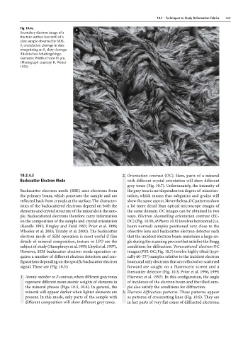
Fig. 10.4c.
Secondary electron image of a
fracture surface (see text) of a
slate sample observed by SEM.
S 2 crenulation cleavage in slate
overprinting an S slaty cleavage.
1
Rheinisches Schiefergebirge,
Germany. Width of view 95 µm.
(Photograph courtesy K. Weber
1976)
10.2.4.3 2. Orientation contrast (OC). Here, parts of a mineral
Backscatter Electron Mode with different crystal orientation will show different
grey tones (Fig. 10.7). Unfortunately, the intensity of
Backscatter electron mode (BSE) uses electrons from the grey tone is not dependent on degree of misorien-
the primary beam, which penetrate the sample and are tation, which means that subgrains and grains will
reflected back from crystals at the surface. The character- show the same aspect. Nevertheless, OC patterns show
istics of the backscattered electrons depend on both the a lot more detail than optical microscope images of
elements and crystal structure of the minerals in the sam- the same domain. OC images can be obtained in two
ple. Backscattered electrons therefore carry information ways. Electron channelling orientation contrast (EC-
on the composition of the sample and crystal orientation OC) (Fig. 10.9b, ×Photo 10.9) involves horizontal (i.e.
(Randle 1992; Dingley and Field 1997; Prior et al. 1999; beam normal) samples positioned very close to the
Wheeler et al. 2003; Trimby et al. 2000). The backscatter objective lens and backscatter electron detector such
electron mode of SEM operation is most useful if fine that the incident electron beam maintains a large an-
details of mineral composition, texture or LPO are the gle during the scanning process that satisfies the Bragg
subject of study (Humphreys et al. 1999; Lloyd et al. 1997). conditions for diffraction. ‘Forescattered’ electron OC
However, SEM backscatter electron mode operation re- images (FSE-OC; Fig. 10.7) involve highly tilted (typi-
quires a number of different electron detectors and con- cally 60–75°) samples relative to the incident electron
figurations depending on the specific backscatter electron beam and only electrons that are reflected or scattered
signal. These are (Fig. 10.3): forward are caught on a fluorescent screen and a
forescatter detector (Fig. 10.3; Prior et al. 1996, 1999;
1. Atomic number or Z contrast, where different grey tones Fliervoet et al. 1997). In this configuration, the angle
represent different mean atomic weights of elements in of incidence of the electron beam and the tilted sam-
the mineral phases (Figs. 10.5, 10.6). In general, the ple also satisfy the conditions for diffraction.
mineral will appear darker when lighter elements are 3. Electron diffraction patterns. These patterns appear
present. In this mode, only parts of the sample with as patterns of crosscutting lines (Fig. 10.8). They are
different composition will show different grey tones. in fact parts of very flat cones of diffracted electrons,