
Page 39 - Modelling in Transport Phenomena A Conceptual Approach
P. 39
20 CHAPTER 2. MOLECULAR AND CONVECTNE TRANSPORT
Analysis
System: Copper slab
Under steady conditions with no internal generation, conservation statement for
energy duces to
Rate of energy in = Rate of energy out = 5000W
Since the slab area across which heat transfer takes place is constant, the heat flux
through the slab is also constant and is given by
5000
4 --- - IOO,OOO w/ m2
' - 0.05
Therefore, the use of Fourier's law of heat conduction, Eq. (2.1-4), gives
r0.04 r35
or,
To = 45.1 "C
2.1.3 Fick's First Law of Diffusion
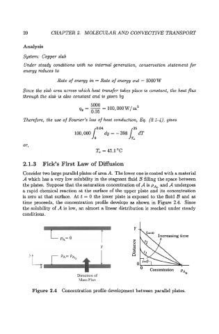
Consider two large parallel plates of area A. The lower one is coated with a material
A which has a very low solubility in the stagnant fluid B filling the space between
the plates. Suppose that the saturation concentration of A is pAo and A undergoes
a rapid chemical reaction at the surface of the upper plate and its concentration
is zero at that surface. At t = 0 the lower plate is exposed to the fluid B and as
time proceeds, the concentration profile develops as shown in Figure 2.4. Since
the solubility of A is low, an almost a linear distribution is reached under steady
conditions.
Increasing time
U
s
'L
X
Concentration
Direction of PA0
Mass Flux
Figure 2.4 Concentration profile development between parallel plates.