
Page 155 - Modern Control Systems
P. 155
Section 2.10 Sequential Design Example: Disk Drive Read System 129
Table 2.10 Typical Parameters for Disk Drive Reader
Parameter Symbol Typical Value
Inertia of arm and
2
read head J 1 N m s /rad
Friction b 20 N m s/rad
Amplifier K a 10-1000
Armature resistance R i n
Motor constant K m 5Nm/A
Armature inductance L lmH
Figure 2.20 with Kb = 0. The model shown in Figure 2.76(b) assumes that the flex-
ure is entirely rigid and does not significantly flex. In Chapter 4, we will consider the
model when the flexure cannot be assumed to be completely rigid.
Typical parameters for the disk drive system are given in Table 2.10.Thus, we have
K„
G(s) =
s(Js + b)(Ls + R)
5000
(2.138)
s(s + 20)(5 + 1000)'
We can also write
K m/(bR)
G(s) = (2.139)
S(T LS + 1)(TS + 1)'
where T L = J/b = 50 ms and T = L/R = 1 ms. Since T <*C T L, we often neglect T.
Then, we would have
KJ(bR) 0.25
G(s)
S(T LS + 1) 5(0.055 + 1)'
or
G(s) =
s(s + 20)
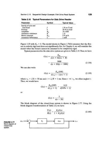
The block diagram of the closed-loop system is shown in Figure 2.77. Using the
block diagram transformation of Table 2.6, we have
Y(s) K aG(s)
(2.140)
R(s) 1 + K aG(s)'
/?(.*) HQ , *« G(s) • Yis)
• ^
FIGURE 2.77 J *
Block diagram of
closed-loop
system.