
Page 154 - Modern Control Systems
P. 154
128 Chapter 2 Mathematical Models of Systems
2.10 SEQUENTIAL DESIGN EXAMPLE: DISK DRIVE READ SYSTEM
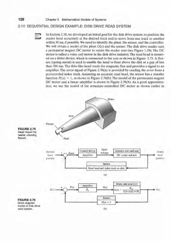
"~f In Section 1.10, we developed an initial goal for the disk drive system: to position the
—4 reader head accurately at the desired track and to move from one track to another
within 10 ms, if possible. We need to identify the plant, the sensor, and the controller.
We will obtain a model of the plant G(s) and the sensor. The disk drive reader uses
a permanent magnet DC motor to rotate the reader arm (see Figure 1.29). The DC
motor is called a voice coil motor in the disk drive industry. The read head is mount-
ed on a slider device, which is connected to the arm as shown in Figure 2.75. A flex-
ure (spring metal) is used to enable the head to float above the disk at a gap of less
than 100 nm.The thin-film head reads the magnetic flux and provides a signal to an
amplifier. The error signal of Figure 2.76(a) is provided by reading the error from a
prerecorded index track. Assuming an accurate read head, the sensor has a transfer
function H(s) = 1, as shown in Figure 2.76(b). The model of the permanent magnet
DC motor and a linear amplifier is shown in Figure 2.76(b). As a good approxima-
tion, we use the model of the armature-controlled DC motor as shown earlier in
Motor
Flexure
FIGURE 2.75
Head mount for
reader, showing
flexure. Head
Input
Desired . „ Control device voltage Actuator and read arm Actual
head ^ ~s, urror Amplifier DC motor and arm head
J *
i
position - . position
Sensor
r> A l J • I 1 J* 1
(a)
Motor and arm G(s)
Amplifier
o E(s) V(s) K.
IHs) • K„ 0(s)' s(Js+b)(Ls+R) - • ns)
Sensor
FIGURE 2.76
Block diagram H{s) = 1
model of disk drive
read system. (b)