
Page 223 - Modern Control Systems
P. 223
Section 3.8 Design Examples 197
management. One of the first to present the nonlinear model in Equations
(3.96-3.98) is Wie et al. [28]. Other related information about the model and the
control problem in general appears in [29-33]. Articles related to advanced control
topics on the space station can be found in [34-40]. Researchers are developing non-
linear control laws based on the nonlinear model in Equations (3.96)-(3.98). Sever-
al good articles on this topic appear in [41-50].
Equation (3.96) represents the kinematics—the relationship between the Euler
angles, denoted by 0 , and the angular velocity vector, fl. Equation (3.97) represents
the space station attitude dynamics. The terms on the right side represent the sum of
the external torques acting on the spacecraft. The first torque is due to inertia cross-
coupling. The second term represents the gravity gradient torque, and the last term is
the torque applied to the spacecraft from the actuators. The disturbance torques (due
to such factors as the atmosphere) are not included in the model used in the design.
Equation (3.98) represents the control moment gyro total momentum.
The conventional approach to spacecraft momentum management design is to de-
velop a linear model, representing the spacecraft attitude and control moment gyro
momentum by linearizing the nonlinear model. This linearization is accomplished by a
standard Taylor series approximation. Linear control design methods can then be readily
applied. For linearization purposes we assume that the spacecraft has zero products of
inertia (that is, the inertia matrix is diagonal) and the aerodynamic disturbances are
negligible. The equilibrium state that we linearize about is
9 = 0,
n =
h = 0,
and where we assume that
h 0 0
I = 0 h 0
0 0 13
In reality, the inertia matrix, I, is not a diagonal matrix. Neglecting the off-diagonal
terms is consistent with the linearization approximations and is a common assumption.
Applying the Taylor series approximations yields the linear model, which as it turns
out decouples the pitch axis from the roll/yaw axis.
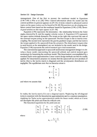
The linearized equations for the pitch axis are
0 0
#2 1 0~ ~ 0 2 ~
2 1
(t)2 3« A 2 0 0 (D 2 + "2, (3.99)
h
0 0 0_ Jh. 1_
where
/3 ~ /1
A, : =
h