
Page 226 - Modern Control Systems
P. 226
200 Chapter 3 State Variable Models
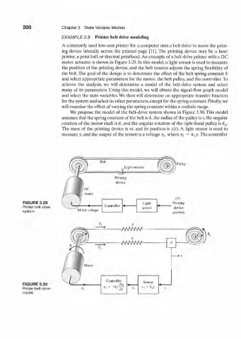
EXAMPLE 3.8 Printer belt drive modeling
A commonly used low-cost printer for a computer uses a belt drive to move the print-
ing device laterally across the printed page [11]. The printing device may be a laser
printer, a print ball, or thermal printhead. An example of a belt drive printer with a DC
motor actuator is shown in Figure 3.29. In this model, a light sensor is used to measure
the position of the printing device, and the belt tension adjusts the spring flexibility of
the belt. The goal of the design is to determine the effect of the belt spring constant k
and select appropriate parameters for the motor, the belt pulley, and the controller. To
achieve the analysis, we will determine a model of the belt-drive system and select
many of its parameters. Using this model, we will obtain the signal-flow graph model
and select the state variables. We then will determine an appropriate transfer function
for the system and select its other parameters, except for the spring constant. Finally, we
will examine the effect of varying the spring constant within a realistic range.
We propose the model of the belt-drive system shown in Figure 3.30. This model
assumes that the spring constant of the belt is k, the radius of the pulley is r, the angular
rotation of the motor shaft is 0, and the angular rotation of the right-hand pulley is 0 p.
The mass of the printing device is m, and its position is y{i). A light sensor is used to
measure y, and the output of the sensor is a voltage v\, where v { = k\y. The controller
Belt
Pulley
Light emitter
=E£
Printing
device
m
FIGURE 3.29 Light
Printer belt-drive Controller sensor Printing
system. Motor voltage device
position
FIGURE 3.30
Printer belt-drive
model.