
Page 227 - Modern Control Systems
P. 227
Section 3.8 Design Examples 201
provides an output voltage t^, where v 2 is a function of V\. The voltage v 2 is connected
to the field of the motor. Let us assume that we can use the linear relationship
=
v 2 2 + k3Vl
~dt
= 0.1 and = 0 (velocity feedback).
and elect to use k 2 k 3
i
The inertia of the motor and pulley s/ = ^motor + -^pulley We plan to use a moderate-
2
DC motor. Selecting a typical 1/8-hp DC motor, we find that J = 0.01 kg m , the field
inductance is negligible, the field resistance is i? = 2(1, the motor constant is
K m — 2 Nm/A, and the motor and pulley friction is b — 0.25 Nms/rad. The radius of
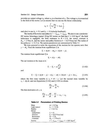
the pulley is r = 0.15 m. The system parameters are summarized in Table 3.1.
We now proceed to write the equations of the motion for the system; note that
y = rd p. Then the tension from equilibrium 7[ is
7J = k(rd - rd p) = k(r0 - y).
The tension from equilibrium T 2 is
T 2 = k(y - re).
The net tension at the mass m is
- = m ^ (3.102)
T x T 2
dt
and
T x-T> = k{rd - y) - k(y - rd) = 2k(rd - y) = 2kx h (3.103)
where the first state variable is X\ = rd — y. Let the second state variable be
= dy/dt, and use Equations (3.102) and (3.103) to obtain
x 2
^ = » „ . (3.104)
dt m l v '
The first derivative of X\ is
=
r
" ~ >
5 f ~ f = 3 x (3105)
-
Table 3.1 Parameters of Printing Device
Mass m = 0.2 kg
Light sensor k x = 1 V/m
Radius r = 0.15 m
Motor
Inductance 1 * 0
Friction b = 0.25 N m s/rad
Resistance R = 2 ft
Constant K„, = 2 Nm/A
Inertia J = / motor + / pu|, ey: J = 0.01 kgm 2