
Page 276 - Modern Control of DC-Based Power Systems
P. 276
236 Modern Control of DC-Based Power Systems
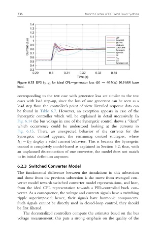
Figure 6.15 ISPS I L15L2 for ideal CPL—generator loss (60 - 40 MW) 30.9 MW base
load.
corresponding to the test case with generator loss are similar to the test
cases with load step-up, since the loss of one generator can be seen as a
load step from the controller’s point of view. Detailed response data can
be found in Table 6.7. However, an exception appears in case of the
Synergetic controller which will be explained in detail successively. In
Fig. 6.14 the bus voltage in case of the Synergetic control shows a “dent”
which occurrence could be understood looking at the currents in
Fig. 6.15. There, an unexpected behavior of the currents for the
Synergetic control appears; the remaining control strategies, where
I L1 5 I L2 display a valid current behavior. This is because the Synergetic
control is completely model-based as explained in Section 5.2; thus, with
an unplanned disconnection of one converter, the model does not match
to its initial definition anymore.
6.2.3 Switched Converter Model
The fundamental difference between the simulations in this subsection
and those from the previous subsection is the move from averaged con-
verter model towards switched converter model representations, and later,
from the ideal CPL representation towards a PID-controlled buck con-
verter. As a consequence, the voltage and currents signals have a switching
ripple superimposed; hence, their signals have harmonic components.
Such signals cannot be directly used in closed-loop control, they should
be first filtered.
The decentralized controllers compute the estimates based on the bus
voltage measurement; this puts a strong emphasis on the quality of the