
Page 280 - Modern Control of DC-Based Power Systems
P. 280
Simulation 239
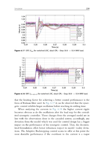
Figure 6.17 ISPS V bus for switched LRC, ideal CPL—Step 30.9 - 53.4 MW load.
Figure 6.18 ISPS I L15L25L3 for switched LRC, ideal CPL—Step 30.9 - 53.4 MW load.
that the limiting factor for achieving a better control performance is the
form of Kalman filter used. In Fig. 6.17 it can be observed that the syner-
getic control exhibits larger oscillation before reaching its settling time.
When analyzing the currents in Fig. 6.18 the higher current ripple
becomes obvious as do the oscillations after the load step for the central-
ized synergetic controller. Those changes from the averaged model are in
line with the observations done in the cascaded system; accordingly, any
deviation from the model which was used for control design has a bigger
impact on the performance of the synergetic control. Thus, the decentra-
lized formulation offers better robustness respect to model reality devia-
tions. The Adaptive Backstepping control seems to offer at this point the
most desirable performance if the overshoot in the current is a major