
Page 281 - Modern Control of DC-Based Power Systems
P. 281
240 Modern Control of DC-Based Power Systems
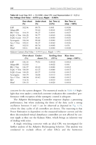
Table 6.8 Load Step 30.9 - 53.4 MW—Ideal CPL Load Representation (t 5 0.25 s)
Bus Voltage (End Value 5 0.9751 p.u.), Ripple B0.485%
Over-shoot Under-shoot Set. Time (s) Rise Time (s)
(%) (%) (2.5%) (step-100%)
LSF 102.96 89.75 0.005 0.0038
Adapt-BS 93.64 0.0041 0.0078
BS 1 Virt 104.19 90.27 0.0041 0.0027
LQG 1 Virt 106.25 90.77 0.0043 0.0026
LQG-Centr 103.27 90.81 0.0050 0.0032
Synergetic 106.04 89.68 0.0080 0.0025
Syn 1 Virt 105.01 90.27 0.0042 0.0026
I&I 102.51 89.74 0.0085 0.070
Hinf 100.6 86.66 0.0080 0.0028
Inductor Current (End Value 5 0.9111 p.u.), Ripple B15%
Over-shoot Under- Settling time Rise time
(%) shoot (%) (15%) (step-100%)
LSF 136.10 79.51 0.0018 0.0012
Adapt-BS 112.83 0.0022 0.001
BS 1 Virt 146.97 69.42 0.0080 0.0012
LQG 1 Virt 150.59 63.22 0.0080 0.0012
LQG-Centr 140.05 83.27 0.0100 0.0012
Synergetic 160.79 34.68 0.0112 0.0012
Syn 1 Virt 148.94 69.42 0.0080 0.0012
I&I 114.15 0.0022 0.0012
Hinf 130.15 0.0020 0.0018
concern for the system designer. The numerical results in Table 6.8 high-
light that even under a switched converter evaluation the controllers’ per-
formance with exception of the synergetic control is adequate.
The Adaptive Backstepping Controller response displays a promising
performance, but when analyzing the form of the duty cycle a strong
oscillation between 0 and 1 can be observed as depicted in Fig. 6.19,
where the duty cycles of all controllers are shown. The reasoning is that
Power Estimation is dependent on the measured inductor current and the
three decentralized virtual disturbance controllers are not affected by cur-
rent ripple as they use the Kalman Filter, which brings an inherent way
of dealing with noise.
A single switching converter with an ideal CPL was investigated for
further analysis of the Adaptive Backstepping behavior. This analysis was
conducted to exclude effects of other LRCs and the harmonics