
Page 284 - Modern Control of DC-Based Power Systems
P. 284
Simulation 243
Figure 6.23 Measured bus voltage and filtered bus voltage for LQG with virtual dis-
turbance—switched CPL representation.
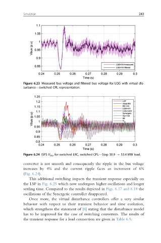
Figure 6.24 ISPS V bus for switched LRC, switched CPL—Step 30.9 - 53.4 MW load.
converter is not smooth and consequently the ripple in the bus voltage
increases by 4% and the current ripple faces an increment of 6%
(Fig. 6.24).
This additional switching impacts the transient response especially on
the LSF in Fig. 6.25 which now undergoes higher oscillations and longer
settling time. Compared to the results depicted in Figs. 6.17 and 6.18 the
oscillations of the Synergetic controller disappeared.
Once more, the virtual disturbance controllers offer a very similar
behavior with respect to their transient behavior and time evolution,
which strengthens the statement of [6] stating that the disturbance model
has to be improved for the case of switching converters. The results of
the transient response for a load connection are given in Table 6.9.