
Page 279 - Modern Control of DC-Based Power Systems
P. 279
238 Modern Control of DC-Based Power Systems
bus voltage measurement which is mainly perturbed by a noise signal
influenced by the switching frequency. Therefore, a 10th-order notch fil-
ter (Butterworth) was used for the voltage. Additionally, for controllers
which use measured currents these were second-order low pass filtered.
Due to this filtering a degradation in performance will occur.
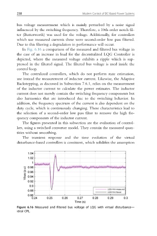
In Fig. 6.16 a comparison of the measured and filtered bus voltage in
the case of an increase in load for the decentralized LQG Controller is
depicted, where the measured voltage exhibits a ripple which is sup-
pressed in the filtered signal. The filtered bus voltage is used inside the
control loop.
The centralized controllers, which do not perform state estimation,
use instead the measurement of inductor current. Likewise, the Adaptive
Backstepping, as discussed in Subsection 7.6.1, relies on the measurement
of the inductor current to calculate the power estimates. The inductor
current does not merely contain the switching frequency components but
also harmonics that are introduced due to the switching behavior. In
addition, the frequency spectrum of the current is also dependent on the
duty cycle, which is continuously changing. These characteristics lead to
the selection of a second-order low pass filter to remove the high fre-
quency components of the inductor current.
The figures presented in this subsection are the evaluation of control-
lers, using a switched converter model. They contain the measured quan-
tities without smoothing.
The transient response and the time evolution of the virtual
disturbance-based controllers is consistent, which solidifies the assumption
Figure 6.16 Measured and filtered bus voltage of LQG with virtual disturbance—
ideal CPL.