
Page 271 - Modern Control of DC-Based Power Systems
P. 271
232 Modern Control of DC-Based Power Systems
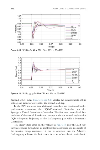
Figure 6.10 ISPS V bus for ideal CPL—Step 30.9 - 53.4 MW.
Figure 6.11 ISPS I L15L25L3 for Ideal CPL and 30.9 - 53.4 MW.
demand of 53.4 MW. Figs. 6.10 and 6.11 display the measurements of bus
voltage and inductor current for the second load step.
In the ISPS test cases two additional controllers are considered in the
performance evaluation: the LQG-Centralized Controller, and the
Synergetic Virtual Disturbance Controller. The first uses a centralized for-
mulation of the virtual disturbance concept while the second replaces the
LQR 1 Setpoint Trajectory or the Backstepping part with a Synergetic
Control law.
The steady-state error on the voltage in Fig. 6.10 after the load step
increase appears throughout all implemented controllers and is a result of
the inserted droop resistances. It can be observed that the Adaptive
Backstepping achieves the best results in terms of overshoot, undershoot,