
Page 269 - Modern Control of DC-Based Power Systems
P. 269
230 Modern Control of DC-Based Power Systems
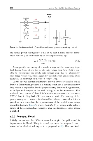
Figure 6.9 Equivalent circuit of the shipboard power system under droop control.
the desired power sharing ratio. It has to be kept in mind that the maxi-
mum value of r d to ensure stability of the loop is defined by:
E k 2V bus
r d , 5 0:878 (6.1)
I max
Subsequently, the tuning of r d results always in a between very tight
load sharing (high r d ) or a low steady-state voltage drop (low r d ). It is pos-
sible to compensate the steady-state voltage drop due to additionally
introduced resistance r d with a secondary control action that consists of an
additional PI controller on the droop control loop.
As the selected control architectures are two-layered controllers which
feature a fast stabilizing control as a primary action and a slower secondary
loop which is responsible for the proper sharing between the generators,
an analysis with respect to the load sharing has to be undertaken. The
analyzed case consists of three LRCs which are connected to the same
MVDC bus, feeding both CPL and resistive loads. The sharing of the
power among the converters is achieved by a droop control that is inte-
grated in each controller; the representation of the model under droop
control is shown in Fig. 6.9, where Controlled V 1,2,3 represent the voltage
output of the corresponding converters after the stabilizing control action
is applied.
6.2.2 Averaged Model
Initially, to evaluate the different control strategies the grid model is
implemented in Matlab. The grid model represents the integrated power
system of an all-electrical ship as it is proposed in [2]. This case study