
Page 270 - Modern Control of DC-Based Power Systems
P. 270
Simulation 231
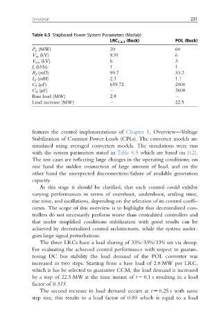
Table 6.5 Shipboard Power System Parameters (Matlab)
LRC 1,2,3 (Buck) POL (Buck)
P n (MW) 20 60
V in (kV) 8.91 6
V out (kV) 6 3
f s (kHz) 1 1
R f (mΩ) 99.7 33.2
L f (mH) 2.1 1.1
C f (μF) 659.72 2000
C if (μF) 3608
Base load (MW) 2.8
Load increase (MW) 22.5
features the control implementations of Chapter 1, Overview—Voltage
Stabilization of Constant Power Loads (CPLs). The converter models are
simulated using averaged converters models. The simulations were run
with the system parameters stated in Table 6.5 which are based on [12].
The test cases are reflecting large changes in the operating conditions; on
one hand the sudden connection of large amount of load, and on the
other hand the unexpected disconnection/failure of available generation
capacity.
At this stage it should be clarified, that each control could exhibit
varying performances in terms of overshoot, undershoot, settling time,
rise time, and oscillations, depending on the selection of its control coeffi-
cients. The scope of this overview is to highlight that decentralized con-
trollers do not necessarily perform worse than centralized controllers and
that under simplified conditions stabilization with good results can be
achieved by decentralized control architectures, while the system under-
goes large signal perturbations.
The three LRCs have a load sharing of 33%/33%/33% set via droop.
For evaluating the achieved control performance with respect to guaran-
teeing DC bus stability the load demand of the POL converter was
increased in two steps. Starting from a base load of 2.8 MW per LRC,
which is has be selected to guarantee CCM, the load demand is increased
by a step of 22.5 MW at the time instant of t 5 0.1 s resulting in a load
factor of 0.515.
The second increase in load demand occurs at t 5 0.25 s with same
step size, this results in a load factor of 0.89 which is equal to a load