
Page 87 - Modern Control of DC-Based Power Systems
P. 87
52 Modern Control of DC-Based Power Systems
within their control loop bandwidth [24,25]. CPLs exhibit negative incre-
mental input impedance, which is the cause of the subsystem interaction
problem and the origin of the undesired destabilizing effect [26]. Although
each subsystem is independently designed to be stand-alone stable, a system
consisting of the cascade of source and load subsystems may exhibit
degraded stability due to subsystem interactions caused by the CPL. This is
because the subsystem interaction affects the bandwidth, the phase, and the
gain margin of each individual converter subsystem [27]. In the past, the
subsystem interaction problem was not significant because an individual
subsystem such as a tightly regulated converter operated under quasiideal
conditions: low source impedance at its input and mainly passive loads at
its output [28]. In modern cascade systems, the subsystem interaction is a
serious issue, as is shown in this section.
2.6.1 The Nyquist Stability Criterion and Its Practical Usage
To address stability issues of a cascade system, several authors have studied
the linearized system under steady-state conditions by defining the source
subsystem and the load subsystem at an arbitrary interface within the
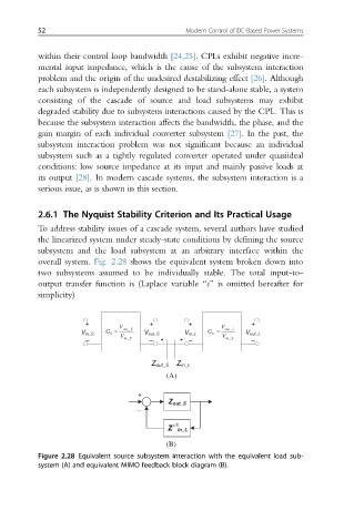
overall system. Fig. 2.28 shows the equivalent system broken down into
two subsystems assumed to be individually stable. The total input-to-
output transfer function is (Laplace variable “s” is omitted hereafter for
simplicity)
+ V + + V +
G = out _ S G = out _ L
V in_S S V V out_S V in_L L V V out_L
– in _ S – – in _ L –
Z out_S Z in_L
(A)
+
Z out_S
–
Z –1 in_L
(B)
Figure 2.28 Equivalent source subsystem interaction with the equivalent load sub-
system (A) and equivalent MIMO feedback block diagram (B).