
Page 86 - Modern Control of DC-Based Power Systems
P. 86
Small-Signal Analysis of Cascaded Systems 51
V o
Sensing
Power stage
i L network
Network analizer
Sensed V o
Channel A
Control signal Sensed i L
Out
Channel B
Control Converted
algorithm i L, V o ADC
Controller
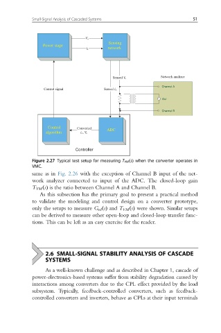
Figure 2.27 Typical test setup for measuring T VM ðsÞ when the converter operates in
VMC.
same as in Fig. 2.26 with the exception of Channel B input of the net-
work analyzer connected to input of the ADC. The closed-loop gain
T VM ðsÞ is the ratio between Channel A and Channel B.
As this subsection has the primary goal to present a practical method
to validate the modeling and control design on a converter prototype,
only the setups to measure G vd ðsÞ and T VM ðsÞ were shown. Similar setups
can be derived to measure other open-loop and closed-loop transfer func-
tions. This can be left as an easy exercise for the reader.
2.6 SMALL-SIGNAL STABILITY ANALYSIS OF CASCADE
SYSTEMS
As a well-known challenge and as described in Chapter 1, cascade of
power-electronics-based systems suffer from stability degradation caused by
interactions among converters due to the CPL effect provided by the load
subsystem. Typically, feedback-controlled converters, such as feedback-
controlled converters and inverters, behave as CPLs at their input terminals