
Page 81 - Modern Control of DC-Based Power Systems
P. 81
46 Modern Control of DC-Based Power Systems
From (2.61), the phase of the inner current controller is
arg G c I ðjω c PICM Þ 52 10:1138 (2.85)
Substituting (2.83) (2.85) into (2.63) and (2.64), the proportional and
integral coefficients can be calculated.
K p I 5 0:1043 (2.86)
K i I 5 2:3388e 1 02 (2.87)
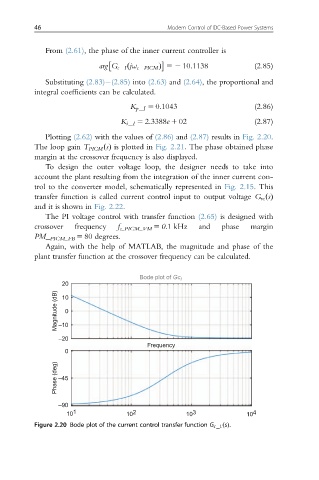
Plotting (2.62) with the values of (2.86) and (2.87) results in Fig. 2.20.
The loop gain T PICM ðsÞ is plotted in Fig. 2.21. The phase obtained phase
margin at the crossover frequency is also displayed.
To design the outer voltage loop, the designer needs to take into
account the plant resulting from the integration of the inner current con-
trol to the converter model, schematically represented in Fig. 2.15. This
transfer function is called current control input to output voltage G vc ðsÞ
and it is shown in Fig. 2.22.
The PI voltage control with transfer function (2.65) is designed with
crossover frequency f c_PICM_VM 5 0.1 kHz and phase margin
PM_ PICM_FB 5 80 degrees.
Again, with the help of MATLAB, the magnitude and phase of the
plant transfer function at the crossover frequency can be calculated.
Bode plot of Gc I
20
Magnitude (dB) –10 0
10
–20
Frequency
0
Phase (deg) –45
–90
10 1 10 2 10 3 10 4
Figure 2.20 Bode plot of the current control transfer function G c I: ðsÞ.