
Page 180 - Modular design for machine tools
P. 180
140 Modular Design Guide and Machine Tools Description
MPS LT LF LP LC LK
PM C*Z C*(X + Y) C*Z*(X + Y) C*(X + Y) + C*Z C*(X + Y)
FGF RAT - - - - -
AM X + Y Z - Z*(X + Y) Z*(Y + X)
Note:
Refer to LTN LFC LTP
JIS B0122 LTH BTP
Tool is BTN LCH LSK
indicated by BTH BFC
hatching LCO
DCN LRC
BRC
LCT MPS; Machining Process Symbol
PM ; Principal Motion
LFR RAT; Rotary Motion Axis of Tool
BFR
AM ; Auxiliary Motion
FGF; Form-Generating Function
(a)
MPS FA FB FC FD FE FF FG FH FI FJ
PM Z Z X + Y X + Y X + Y C C C*(X + Y) C*(X + Y) + X*Y C*Z
FGF RAT DX + DY DX + DY DX + DY DZ DZ DX + DY DZ DX + DY DZ DX + DZ
AM C*(X + Y) C*X*Y C*Z*(Y + X) C*Z C*Z*(Y + X) Z*(X + Y) Z*(X + Y) Z Z X + Y
(b)
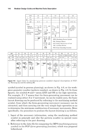
Figure 4-8 Input data by machining process symbol—logical description of FGF:
(a) Turning [L] and (b) milling [F].
symbol (symbol in process planning), as shown in Fig. 4-8, or the work-
piece geometry number (pattern number), as shown in Fig. 4-9. In these
figures, the symbols ● and + mean AND and OR in the logic operation.
For example, X + Y means that the form-generating movement can be
realized using either X or Y movement. As can be readily seen, the basic
layout drawing can be produced by referring to the machining method
symbol, from which the form-generating movement necessary can be
extracted, and then carrying out the very simple logic operation so as
to determine the minimum combination of necessary movements. More
specifically, the procedure to produce the layout drawing is as follows.
1. Input of the necessary information, using the machining method
symbol in principle and also the pattern number in special cases
after referring to the part drawing.
2. Reference to the data file for comparing the MPS (machining process
symbol) to the FGF (form-generating function), which was prepared
beforehand.