
Page 183 - Modular design for machine tools
P. 183
Application of Machine Tool Description to Engineering Design 143
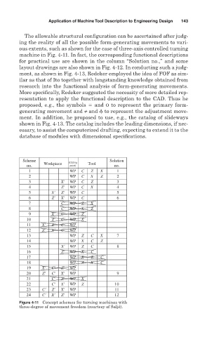
The allowable structural configuration can be ascertained after judg-
ing the reality of all the possible form-generating movements to vari-
ous extents, such as shown for the case of three-axis controlled turning
machine in Fig. 4-11. In fact, the corresponding functional descriptions
for practical use are shown in the column “Solution no.,” and some
layout drawings are also shown in Fig. 4-12. In conducting such a judg-
ment, as shown in Fig. 4-13, Redeker employed the idea of FOF as sim-
ilar as that of Ito together with longstanding knowledge obtained from
research into the functional analysis of form-generating movements.
More specifically, Redeker suggested the necessity of more detailed rep-
resentation to apply the functional description to the CAD. Thus he
proposed, e.g., the symbols and O to represent the primary form-
generating movement and ≠ and to represent the adjustment move-
ment. In addition, he proposed to use, e.g., the catalog of slideways
shown in Fig. 4-13. The catalog includes the leading dimensions, if nec-
essary, to assist the computerized drafting, expecting to extend it to the
database of modules with dimensional specifications.
Scheme (Cutting Solution
no. Workpiece point) Tool no.
1 WP C Z X 1
2 WP C X Z 2
3 X' WP C Z 3
4 Z' WP C X 4
5 X' Z' WP C 5
6 Z' X' WP C 6
7 C' WP Z X
8 C' WP X Z
9 X' C' WP Z
10 Z' C' WP X
11 X' Z' C' WP
12 Z' X' C' WP
13 WP Z C X 7
14 WP X C Z
15 X' WP Z C 8
16 Z' WP X C
17 WP X Z C
18 WP Z X C
19 X' C' Z' WP
20 Z' C' X' WP 9
21 C' Z' WP X
22 C' X' WP Z 10
23 C' Z' X' WP 11
24 C' X' Z' WP 12
Figure 4-11 Concept schemes for turning machines with
three-degree of movement freedom (courtesy of Saljé).