
Page 179 - Modular design for machine tools
P. 179
Application of Machine Tool Description to Engineering Design 139
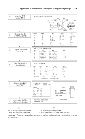
1 Input the WGN INPUT:21*31*LF*LT*DC*DS
and/or MPS LT LF
LF LT LF DS DC
21 31
Refer to the file WGN MPS PM RAT AM
2 of MPS and FGF 21 FA Z DX + DY C*(X + Y)
PA Z DX + DY C*(Y + X)
31 FD X + Y DZ C*Z
PB X + Y DY + DX C*Z
$$ LF C*(X + Y) - Z
$$ LT C*Z - X + Y
$$ DC Z DZ -
$$ DS X + Y DX+DY C*Z
RESULT, EACH COMBINATION
3 Logical operation NO PM RAT AM
of FGF 1 C*(X + Y)*Z (DX + DY)*DZ -
2 C*(X + Y)*Z DX*DY*DZ -
3 C*X*Y*Z (DX + DY)*DZ -
4 C*(X + Y)*Z (DX + DY)*DZ Y + X
5 C*(X + Y)*Z DX*DY*DZ Y + X
6 C*X*Y*Z (DX + DY)*DZ -
Decision-making SELECT: HP, HA, HR
4 for selection
WGN MPS PM RAT AM
21 FA Z DX + DY C*(X + Y)
31 FD X + Y DZ C*Z
$$ LF C*(X + Y) - Z
$$ LT C*Z - X + Y
$$ DC Z DZ -
$$ DS X + Y DX + DY C*Z
RESULT, PM RAT AM
C*(X + Y)*Z (DX + DY)*DZ -
5 Conversion FGF FGF: C*X*Z, DX*DZ
into FDMT OPT: NO DX*DZ = SY
FDMT Work
C /XZ /SY
C /ZX /SY
CX /Z /SY
CZ /X /SY
CXZ / /SY
CZX / /SY Main spindle
Automatic drafting DRAWING: CZ/X/SY-DX CZ/X/SY-DX
6
of concept drawing DRAWING: ED
(a) (b)
WGN : Workpiece geometry number FGF : Form-generating function
MPS : Machining process symbol FDMT : Functional description of machine tool
Figure 4-7 Flowchart for producing concept drawing: (a) Operational steps and (b) example
of execution.