
Page 181 - Modular design for machine tools
P. 181
Application of Machine Tool Description to Engineering Design 141
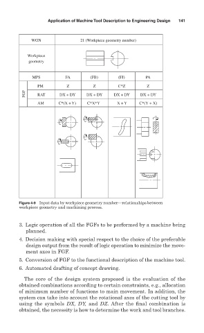
WGN 21 (Workpiece geometry number)
Workpiece
geometry
MPS FA (FB) (FJ) PA
PM Z Z C*Z Z
FGF RAT DX + DY DX + DY DX + DY DX + DY
AM C*(X + Y) C*X*Y X + Y C*(Y + X)
Figure 4-9 Input data by workpiece geometry number—relationships between
workpiece geometry and machining process.
3. Logic operation of all the FGFs to be performed by a machine being
planned.
4. Decision making with special respect to the choice of the preferable
design output from the result of logic operation to minimize the move-
ment axes in FGF.
5. Conversion of FGF to the functional description of the machine tool.
6. Automated drafting of concept drawing.
The core of the design system proposed is the evaluation of the
obtained combinations according to certain constraints, e.g., allocation
of minimum number of functions to main movement. In addition, the
system can take into account the rotational axes of the cutting tool by
using the symbols DX, DY, and DZ. After the final combination is
obtained, the necessity is how to determine the work and tool branches.