
Page 219 - Book Hosokawa Nanoparticle Technology Handbook
P. 219
4.3 NANOPORE STRUCTURE FUNDAMENTALS
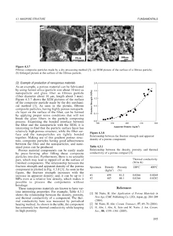
Figure 4.3.7
Fibrous composite particles made by a dry processing method [3]. (a) SEM picture of the surface of a fibrous particle;
(b) Enlarged picture at the surface of the fibrous particle.
(2) Example of production of nanoporous materials 2.0
As an example, a porous material can be fabricated
by using fumed silica (particle size about 10 nm) as 1.6
nanoparticle and glass fiber as fibrous particle
(fiber diameter about 10 m, length about 3 mm). 1.2
Figure 4.3.7 shows the SEM pictures of the surface
of the composite particle made by the dry mechani- Fracture Strength (MPa)
cal method [3]. As seen in the picture, fibrous 0.8
composite particles, having highly porous nanoparti-
cle layer on the surface of the fiber, can be formed 0.4
by applying proper stress conditions that will not
break the glass fibers in the particle composing
process. Examining the bonded interface between 0.0 300 350 400 450 500
the fiber and the nanoparticle with the SEM, it is Apparent Density (kg/m )
3
interesting to find that the particle surface layer has
relatively high porous structure, while the fiber sur- Figure 4.3.8
face and the nanoparticles are tightly bonded Relationship between the fracture strength and apparent
together. Making use of this gradient porous struc- density of a porous component.
ture, composite particles having good adhesiveness
between the fiber and the nanoparticles, and nano-
sized pores can be produced. Table 4.3.1
Porous material components can be easily made Relationship between the density, porosity, and thermal
by press-forming after filling these composite conductivity of a porous compact [3].
particles into dies. Furthermore, there is no unstable
part, which may lead to ripped-off at the surface of Thermal conductivity
finished components. The relationship between the (W/m K)
fracture strength and apparent density of the porous Specimen Density Porosity 100 C 400 C
o
o
component is plotted in Fig. 4.3.8 [3]. As seen in the (kg/m ) (%)
3
figure, the fracture strength increases with the
increase in apparent density; and, it can be up to 1 #1 459 81.2 0.0266 0.0269
MPa even at a relative low density, which makes it #2 485 80.1 0.0266 0.0282
possible to process the components without
breakage.
These nanoporous materials are known to have var- References
ious interesting properties. For example, Table 4.3.1 [1] M. Naito, H. Abe: Application of Porous Materials in
shows the relationship between the density, porosity,
and thermal conductivity of a component. The ther- New Age, CMC Publishing Co. LTD., Japan, pp. 204–209
mal conductivity here was measured by periodical (2004).
heating method. As shown in the table, the component [2] M. Naito, H. Abe: Ceram. Transact., 57, 69–76 (2004).
has extremely low thermal conductivity while keeping [3] H. Abe, I. Abe, K. Sato and M. Naito: J. Am. Ceram.
its high porosity. Soc., 88, 1359–1361 (2005).
195