
Page 250 - Book Hosokawa Nanoparticle Technology Handbook
P. 250
FUNDAMENTALS CH. 4 CONTROL OF NANOSTRUCTURE OF MATERIALS
4.5.2 Low temperature cofired ceramics (LTCC) materials accumulated with low-electroconductive
materials and HIC. These have been widely used in
(1) Features of LTCC industry to produce supercomputer mainframe boards
Low temperature cofired ceramics (LTCC) is a and automobile module boards. Since the low-
ceramic material, including an inner conductive metal electroresistant material can be used as inner wiring, its
with low resistance and melting point, which can be potential for use in applications for light, high-density,
sintered together simultaneously. Low-electroresist- high-frequency boards, and module parts with moving
ing metals, such as Ag, Au, and Cu, are mainly element functions has attracted considerable attention.
applied for the metal part of LTCC, while the cofiring A typical structure of the board is shown in Fig. 4.5.8.
temperature of these low-electroresisting metals, with
a melting point of around 1,000°C, is set about 900°C (2) Classification of LTCC materials
below the melting point of the metal. LTCC materials are classified into three types;
The major features required for the LTCC board namely (1) “Glass composite system” made by mix-
are (1) thermal expansion coefficient, (2) low ing aggregates like Al O and glass, (2) “Crystallized
2
3
dielectricity, (3) low dielectric loss, and (4) low glass system” generated as crystals from the glass,
electroconductor loss during the cofiring with the and (3) “Non-glass system “ firing only the starting
low-electroresisting material. The production material at a lower temperature without adding glass.
process for a multi-layer ceramic board widely using The major materials previously developed and
LTCC is shown in Fig. 4.5.7. applied are shown in Table 4.5.1. The bending
The LTCC was developed in the 1980s, targeting an strength of most materials is about 200 MPa and their
increased number of layers of hybrid IC (HIC) board dielectric constant is less than 10. The average
and applying the technology to handle the resistant particle size of the glass and Al O used for LTCC
2
3
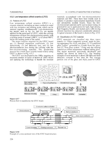
Figure 4.5.7
Process flow to manufacture the LTCC board.
Figure 4.5.8
Example of a cross-sectional view of the LTCC board structure.
226