
Page 254 - Book Hosokawa Nanoparticle Technology Handbook
P. 254
4.5 STRUCTURE CONTROL OF NANOPARTICLE COLLECTIVES BY SINTERING AND BONDING FUNDAMENTALS
As shown in Fig. 4.5.10, the amount of post- 900°C. Data marked with D in the figure were
anorthite firing increases with the decreasing Al O par- obtained by initially adding the anorthite and the oth-
3
2
ticle size, leading to a corresponding drop in the thermal ers, marked with A, B, and C, by controlling Al O 3
2
expansion coefficient. The increase of anorthite due to particles to change the anorthite amount.
the prolonged firing time also causes its reduction. It is presumed that strength is influenced, not only
The anorthite is considered to be a product of the by the anorthite amount but also the difference in the
reaction between Al O and glass and the microstruc- structure shown in Fig. 4.5.12. As seen in Fig. 4.5.11,
3
2
ture is reportedly very important in obtaining the there is a tendency for the bending strength in air and
required board strength. Figure 4.5.11 shows the water to increase, with the increasing anorthite
bending strength of the sample piece with a different amount leading to an improvement in the depression
mass fraction of anorthite by firing Al O and glass at of stress corrosion. However, under the condition of
3
2
D, the strength decreases despite the rise in the anor-
thite amount, which suggests the considerable influ-
ence of many initial defects. As well as the anorthite
amount, the microstructure with the anorthite
between the Al O particles and the glass is consid-
3
2
ered to contribute toward the improvement of the
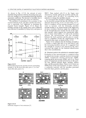
strength by the crack, as shown in Fig. 4.5.12.
Figure 4.5.11 indicates that the bending strength in
a vacuum is higher than that in air and reduces with
the increasing anorthite amount. It is suggested that
the strength in vacuum is not affected by the stress
corrosion but simply by the hindered densification
due to the crystallization.
(4) Structural control in the submicron to nanosized region
Evaluation of the microstructure is conducted using
an optical microscope, scanning electron microscope
(SEM), transmission electron microscope (TEM),
scanning probe microscope (SPM), and so on. These
pieces of equipment provide information on the parti-
cle size, sintered particle shape, necking, surface
Figure 4.5.11 state, and the generated phase. Figure 4.5.13 shows an
Relationship between the anorthite amount and bending SEM picture of the microstructure of LTCC, which is
strength (A, B: Pb-Al O -SiO -B O glass, C, D: CaO- a composite material, with the anorthite generated
3
2
2
3
2
Al O -SiO -B O glass) [3]. from the Al O particles and the glass.
2
2
3
2
3
3
2
Figure 4.5.12
Schematic diagram of microstructure [3].
229