
Page 258 - Book Hosokawa Nanoparticle Technology Handbook
P. 258
4.5 STRUCTURE CONTROL OF NANOPARTICLE COLLECTIVES BY SINTERING AND BONDING FUNDAMENTALS
4.5.4 Joining by FSW Only the probe is forced into the material during weld-
ing, and the tool is moved along the interface. The
4.5.4.1 Friction stir welding material is restricted to the back plate. The joining is
Friction stir welding (FSW) has already entered the performed by plastic flow caused by the tool in the
practical use stage in various industrial fields such as solid state. Because the peak temperature does not
railroad vehicles, vessels, structures, and cars [1–5], reach the melting point and the material is in the solid
after it was developed by TWI (British Welding state at this time, the grains are refined, the decrease in
Institute) in 1991 [6, 7]. Research and development in the strength by welding is much lower than that of
this area has significantly increased in every country fusion welding, and, in some cases, the strength of the
around the world. In this joining method, as shown in joints is higher than that of the base metal. The details
Fig. 4.5.19(a), the columnar rotating tool at a high of the tool are to be referred to a textbook on FSW [8].
speed contacts the materials to produce frictional heat, A schematic diagram of the cross-sectional
and the materials can then be joined using the fric- microstructure of the welded part is shown in
tional heat. As shown in Fig. 4.5.19(b), the tool con- Fig. 4.5.20. The center, called the stir zone, consists of
sists of a large shoulder part and a probe part at the tip. a recrystallized microstructure which consists of
equiaxial grains of hundreds of nanometers to several
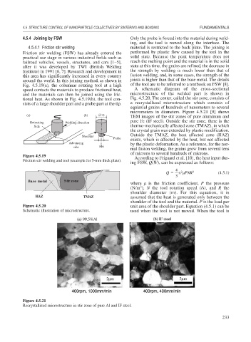
micrometers in diameters. Figure 4.5.21 [9] shows
(a) (b) ∅15
TEM images of the stir zones of pure aluminum and
pure Fe (IF steel). Outside the stir zone, there is the
Retreating Welding direction
Side thermo-mechanically affected zone (TMAZ), in which
the crystal grain was extended by plastic modification.
Outside the TMAZ, the heat affected zone (HAZ)
Sho ulder
Probe
exists, which is affected by the heat, but not affected
Advancing by the plastic deformation. As a reference, for the nor-
side M6
mal fusion welding, the grains grow from several tens
of microns to several hundreds of microns.
Figure 4.5.19 According to Frigaard et al. [10], the heat input dur-
Friction stir welding and tool (example for 5-mm thick plate).
ing FSW, Q(W), can be expressed as follows:
4
Q PNR 3 (4.5.1)
2
3
Base metal Stir zone
where is the friction coefficient, P the pressure
3
(N/m ), N the tool rotation speed (/s), and R the
shoulder diameter (m). For this equation, it is
HAZ TMAZ assumed that the heat is generated only between the
shoulder of the tool and the material. P is the load per
Figure 4.5.20 unit area of the shoulder part. Equation (4.5.1) can be
Schematic illustration of microstructure. used when the tool is not moved. When the tool is
Figure 4.5.21
Recrystallized microstructure in stir zone of pure Al and IF steel.
233