
Page 141 - New Trends In Coal Conversion
P. 141
104 New Trends in Coal Conversion
(a) (b)
Moisture
Dry shell
Raw fuel Dry fuel Char Ash
Wet core
Inert Volatile Char Inert
heating release oxidation heating
TIME
Sequential conversion model
Volatile flame
(visible)
Ash
(c) Char
Dry fuel
Raw fuel
Char oxidation
(no visible flame) Simultaneous conversion model
Particle conversion
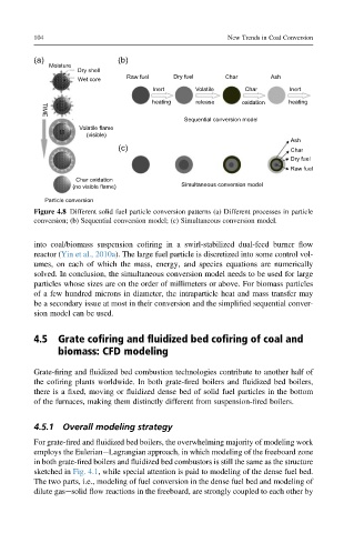
Figure 4.8 Different solid fuel particle conversion patterns (a) Different processes in particle
conversion; (b) Sequential conversion model; (c) Simultaneous conversion model.
into coal/biomass suspension cofiring in a swirl-stabilized dual-feed burner flow
reactor (Yin et al., 2010a). The large fuel particle is discretized into some control vol-
umes, on each of which the mass, energy, and species equations are numerically
solved. In conclusion, the simultaneous conversion model needs to be used for large
particles whose sizes are on the order of millimeters or above. For biomass particles
of a few hundred microns in diameter, the intraparticle heat and mass transfer may
be a secondary issue at most in their conversion and the simplified sequential conver-
sion model can be used.
4.5 Grate cofiring and fluidized bed cofiring of coal and
biomass: CFD modeling
Grate-firing and fluidized bed combustion technologies contribute to another half of
the cofiring plants worldwide. In both grate-fired boilers and fluidized bed boilers,
there is a fixed, moving or fluidized dense bed of solid fuel particles in the bottom
of the furnaces, making them distinctly different from suspension-fired boilers.
4.5.1 Overall modeling strategy
For grate-fired and fluidized bed boilers, the overwhelming majority of modeling work
employs the EulerianeLagrangian approach, in which modeling of the freeboard zone
in both grate-fired boilers and fluidized bed combustors is still the same as the structure
sketched in Fig. 4.1, while special attention is paid to modeling of the dense fuel bed.
The two parts, i.e., modeling of fuel conversion in the dense fuel bed and modeling of
dilute gasesolid flow reactions in the freeboard, are strongly coupled to each other by