
Page 311 - Numerical Methods for Chemical Engineering
P. 311
300 6 Boundary value problems
2 2
1 1
2 2
1 1
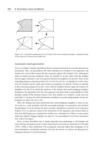
Figure 6.25 Automatic partitioning of a 2-D region into nonoverlapping triangles, subsequent steps
in the clockwise direction from upper left.
Automatic mesh generation
Here we consider a simple algorithm to form a nonstructured grid on a closed region in two
dimensions. First, we parameterize the outer boundary as a number of line segments, and
number the vertices that connect the line segments (upper left in Figure 6.25). Subsequent
steps are shown moving clockwise. Next, we identify (1) as the vertex with the smallest
interior angle, and draw a new line segment between its neighbors (2) and (6). Then, in the
remaining polygon connecting nodes (2)–(3)–(4)–(5)–(6)–(2), we identify (3) as the vertex
with the smallest interior angle and connect its neighbors (2) and (4). Finally, we identify
in the remaining polygon (6) as the vertex with the smallest interior angle and connect its
neighbors (2) and (5) to finish the partition of the domain into nonoverlapping triangles.
Sometimes, the algorithm calls for a line segment to be drawn that is unacceptable as it lies
partially outside of the domain (Figure 6.26). The remedy is to identify a node, here (4),
such that (1)–(4) does lie within the domain, and then to proceed independently for the two
polygons on either side of (1)–(4).
Once the domain has been partitioned into nonoverlapping triangles to form an ini-
tial mesh (i.e., node positions with the associated topology of connections that describe
the partition), it can be refined for more accurate calculations. In global mesh refinement
(Figure 6.27), we add new nodes at the mid-points of the segments, and connect them so
that each old triangle now contains four smaller ones. Alternatively, if there is some region
where the solution changes rapidly, say near (2), we can perform a local mesh refinement
only within this region.
Here, we have described only a simple algorithm for partitioning a 2-D domain, but
more efficient alternatives (also in three dimensions) exist and are described in O’Rourke
(1993). FEM is often performed with rectangular elements rather than triangular (or in
three dimensions, tetrahedral) elements, but here for brevity we restrict our discussion to
triangular elements in two dimensions.