
Page 312 - Numerical Methods for Chemical Engineering
P. 312
The finite element method 301
2
2
1 1
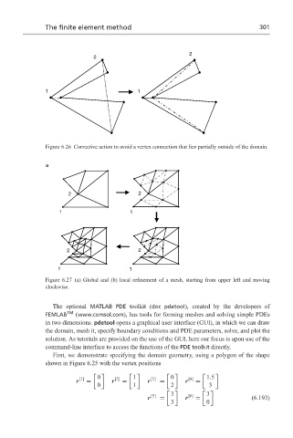
Figure 6.26 Corrective action to avoid a vertex connection that lies partially outside of the domain.
a
2 2
1 1
2 2
1 1
Figure 6.27 (a) Global and (b) local refinement of a mesh, starting from upper left and moving
clockwise.
The optional MATLAB PDE toolkit (doc pdetool), created by the developers of
FEMLAB TM (www.comsol.com), has tools for forming meshes and solving simple PDEs
in two dimensions. pdetool opens a graphical user interface (GUI), in which we can draw
the domain, mesh it, specify boundary conditions and PDE parameters, solve, and plot the
solution. As tutorials are provided on the use of the GUI, here our focus is upon use of the
command-line interface to access the functions of the PDE toolkit directly.
First, we demonstrate specifying the domain geometry, using a polygon of the shape
shown in Figure 6.25 with the vertex positions
0 [2] 1 [3] 0 [4] 1.5
[1]
r = r = r = r =
0 1 2 3
3 [6] 3
[5]
r = r = (6.193)
3 0