
Page 449 - Offshore Electrical Engineering Manual
P. 449
436 CHAPTER 2 Preparation and Use of Performance Standards
(B)
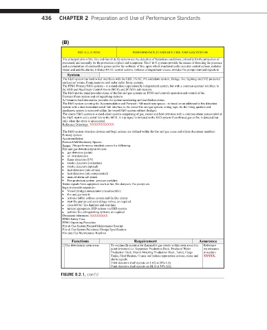
INSTALLATION: PERFORMANCE STANDARD: FIRE AND GAS SYSTEM
The principal aims of the Fire and Gas (F & G) systems are the detection of hazardous conditions, primarily for the protection of
personnel, and secondly for the protection of plant and equipment. The F & G systems provide the means of detecting the presence
and accumulation of combustible gasses and/or the outbreak of fire, upon which it automatically executes control actions, initiates
visual and audible alarms, initiates HVAC control actions, initiates extinguishant release, initiates fire pumps start and signals to
h System
The F&G system has hard wired interfaces with the ESD, HVAC, PA and alarm system, Deluge Fire Fighting and CO2 protected
enclosures/ rooms, Foam monitors and under pallet Spray systems.
The FPSO Primary F&G systems -is a stand-alone (operationally independent) system, but with a common operator interface to
the ESD and Machinery Control Room (MCR) and SCADA sub-systems.
The F&G matrix panel provides status of the fire and gas systems on FPSO and controls operation and control of the
firewater/foam system and extinguishing systems.
A Common Facilities matrix provides for system monitoring and fault/failure status.
The F&G system covering the Accommodation and Forward / Aft machinery spaces -is based on an addressable fire detection
system with a dual redundant serial link interface to the vessel fire and gas system, voting logic for the living quarters and
machinery spaces is executed within the vessel F&G system cabinet (bridge).
The cranes F&G system is a stand-alone system comprising of gas, smoke and heat detection with a common alarm annunciated at
the F&G matrix and a serial link to the MCR. A trip signal is initiated to the ESD system if confirmed gas or fire is detected but
only when the crane is unoccupied.
Reference Drawings: XXXXXXXXXXX
The F&G system detection devices and logic actions are defined within the fire and gas cause and effects document numbers:
Primary system:
Accommodation:
Forward/Aft Machinery Spaces:
Scope: This performance standard covers the following:
Fire and gas detection input devices:
∑ gas detectors (point)
∑ oil mist detectors
∑ flame detectors (UV)
∑ smoke detectors (ionisation)
∑ smoke detectors (optical)
∑ heat detectors (rate of rise)
∑ heat detectors (rate compensated)
∑ manual alarm call points
∑ Fire protection system pressure switches
Status signals from equipment such as fan, fire dampers, fire pumps etc.
logic to provide outputs to:
∑ Vessel (bridge) annunciator (visual/audible)
∑ fire and gas matrix
∑ activate public address system and facility alarms
∑ start fire pumps and open deluge valves, as required
∑ close HVAC fire dampers and stop fans
∑ initiate appropriate ESD actions via ESD system
∑ activate fire extinguishing systems, as required
Document references: XXXXXXXX
FPSO Safety Case
FPSO Operating Procedure
Fire & Gas System Planned Maintenance Routine
Fire & Gas System Functional Design Specification:
Fire and Gas Maintenance Routines
Functions Requirement Assurance
1 Gas detection in open areas. To continually monitor for flammable gas clouds within open areas (via Reference
point detectors) i.e. Separation Production Deck, Produced Water maintenance
Production Deck, Export Metering Production Deck, Turret, Cargo procedure
Tanks, Fired Heaters, Cranes and initiate appropriate actions, status and XXXXX.
alarm signals.
Point detectors shall operate on LLG at 20% LEL
Point detectors shall operate on HLG at 50% LEL
FIGURE 9.2.1, cont’d